
Installation / Operation Instruction Manual

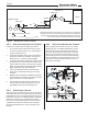


Table Of Contents
- Cover
- TABLE OF CONTENTS
- General Information
- SECTION 2 Venting and Combustion Air
- SECTION 3 Gas supply and Piping
- SECTION 4 Water Flow and Headloss Data
- SECTION 5 Boiler Piping
- SECTION 6 Condensate Drain Trap
- SECTION 7 Electrical Connections
- 7.A Installation Warnings
- 7.B Main Power Connections
- 7.C Main Power Data
- 7.D Control Panel Layout
- 7.E Field Connections
- 7.E.1 Power
- 7.E.2 Dry Contacts
- 7.E.3 Temperature Sensors
- 7.E.4 Safety Chain
- 7.E.5 Isolation Valve
- 7.E.6 Heat Demands
- 7.E.7 Analog In and Analog Out
- 7.E.8 Dry Contacts. Run & Alarm
- 7.E.9 RS 485 for Cascade (Lead Lag)
- 7.E.10 RS485 BMS
- 7.F Modbus to BACnet Memory Map (4 pages)
- 7.G WiringDiagram
- 7.H High Voltage Wiring Diagrams (5 pages)
- 7.I Ladder Diagrams (8 pages)
- SECTION 8 Control Operation
- 8.A The Home Screen
- 8.B Login to Lock / Unlock the Display Screen
- 8.C Quick Start
- 8.D Configuration
- 8.E Service Screens
- 8.E.1 Burner
- 8.E.2 Digital I/O ( Input / Output )
- 8.E.3 Analog I/O
- 8.E.4 Screen Settings Timeout
- 8.E.5 History
- 8.E.6 Restart Touchscreen & Recalibrate
- 8.E.7 Factory Reset
- 8.E.8 HMI Model OEM only
- 8.E.9 BIC Model OEM only
- 8.E.10 Both Model. OEM only.
- 8.E.11 About (the Firmware)
- 8.E.12 O2 (Trim Set Point)
- 8.E.13 LMV
- 8.F Messages and USB
- 8.G Active Demands
- SECTION 9 Parameter Tables (3 pages)
- SECTION 10 Initial startupInstructions
- SECTION 11 Maintenance
- SECTION 12 Troubleshooting
- SECTION 13 Replacement Parts
- 13.A Frame and Jacket Assembly, Part Numbers
- 13.B Control Panel Assembly, Part Numbers
- 13.C Blower and Burner Assembly,Part Numbers. ALL Sizes
- 13.D AC Distribution Box Assemblies and Part Numbers
- 13.E Burner Door Part Numbers
- 13.F Waterway Inlet Assembly, Part Numbers
- 13.G Waterway Outlet Assembly, Part Numbers
- 13.H Gas Train Part Numbers
- 13.I Exhaust Manifold Part Numbers

Page 21
Figure 5. Combustion Air and Vent Through Side-wall.
U.S. Installations (see note 1) Canadian Installations (see note 2)
A= Clearance above grade, veranda, porch, 12 inches (30 cm) 12 inches (30 cm)
deck, or balcony See note 6 See note 6
B= Clearance to window or door that may be Direct vent only: 12 inches (30 cm); 36 inches (91 cm)
opened Other than Direct vent: 4 ft (1.2m) below or to
side of opening; 1 ft (30 cm) above opening
C= Clearance to permanently closed window See note 4 See note 5
D= Vertical clearance to ventilated sot located
above the terminal within a horizontal See note 4 See note 5
distance of 2 feet (61 cm) from the center
line of the terminal
E= Clearance to unventilated sot See note 4 See note 5
F= Clearance to outside corner See note 4 See note 5
G= Clearance to inside corner See note 4 See note 5
H= Clearance to each side of center line 3 feet (91 cm) within a height 15 feet
extended above meter/regulator assembly See note 4 above the meter/regulator assembly
I= Clearance to service regulator vent outlet See note 4 3 feet (91 cm)
J= Clearance to non-mechanical air supply Direct vent only: 36” (91cm)
inlet to building or the combustion air inlet Other than Direct vent: 4 ft (1.2m) below 36 inches (91 cm)
to any other unit or to side of opening; 1 ft (30 cm) above opening
K= Clearance to a mechanical air supply inlet 3 feet (91 cm) above if within 10 feet (3 m) 6 feet (1.83 m)
horizontally
L= Clearance above paved sidewalk or paved Vent termination not allowed in this location 7 ft (2.1 m)
driveway located on public property for category IV units. See note 5
M= Clearance under veranda, porch, deck, See note 4 12 inches (30 cm)
or balcony See note 5
Notes:
1. In accordance with the current ANSI Z223.1 / NFPA 54 National Fuel Gas Code.
2. In accordance with the current CAN/CSA-B149 Installation Codes.
3. Permitted only if veranda, porch, deck, or balcony is fully open on a minimum of two sides beneath the oor.
4. For clearances not specied in ANSI Z223.1 / NFPA 54, clearance is in accordance with local installation codes and the
requirements of the gas supplier.
5. For clearances not specied in CAN/CSA-B149, clearance is in accordance with local installation codes and the requirements of the
gas supplier.
6. IMPORTANT: All terminals must be placed so that they remain a minimum 12” above expected snow line. Local codes may have
more specic requirements, and must be consulted.
*When vent terminal is less than 10 feet (3 m)
horizontally from a forced air inlet, the terminal must
be at least 3 feet (0.9 m) above the air inlet. (US only)