
Installation / Operation Instruction Manual


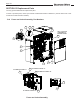


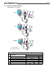


Table Of Contents
- Cover
- TABLE OF CONTENTS
- General Information
- SECTION 2 Venting and Combustion Air
- SECTION 3 Gas supply and Piping
- SECTION 4 Water Flow and Headloss Data
- SECTION 5 Boiler Piping
- SECTION 6 Condensate Drain Trap
- SECTION 7 Electrical Connections
- 7.A Installation Warnings
- 7.B Main Power Connections
- 7.C Main Power Data
- 7.D Control Panel Layout
- 7.E Field Connections
- 7.E.1 Power
- 7.E.2 Dry Contacts
- 7.E.3 Temperature Sensors
- 7.E.4 Safety Chain
- 7.E.5 Isolation Valve
- 7.E.6 Heat Demands
- 7.E.7 Analog In and Analog Out
- 7.E.8 Dry Contacts. Run & Alarm
- 7.E.9 RS 485 for Cascade (Lead Lag)
- 7.E.10 RS485 BMS
- 7.F Modbus to BACnet Memory Map (4 pages)
- 7.G WiringDiagram
- 7.H High Voltage Wiring Diagrams (5 pages)
- 7.I Ladder Diagrams (8 pages)
- SECTION 8 Control Operation
- 8.A The Home Screen
- 8.B Login to Lock / Unlock the Display Screen
- 8.C Quick Start
- 8.D Configuration
- 8.E Service Screens
- 8.E.1 Burner
- 8.E.2 Digital I/O ( Input / Output )
- 8.E.3 Analog I/O
- 8.E.4 Screen Settings Timeout
- 8.E.5 History
- 8.E.6 Restart Touchscreen & Recalibrate
- 8.E.7 Factory Reset
- 8.E.8 HMI Model OEM only
- 8.E.9 BIC Model OEM only
- 8.E.10 Both Model. OEM only.
- 8.E.11 About (the Firmware)
- 8.E.12 O2 (Trim Set Point)
- 8.E.13 LMV
- 8.F Messages and USB
- 8.G Active Demands
- SECTION 9 Parameter Tables (3 pages)
- SECTION 10 Initial startupInstructions
- SECTION 11 Maintenance
- SECTION 12 Troubleshooting
- SECTION 13 Replacement Parts
- 13.A Frame and Jacket Assembly, Part Numbers
- 13.B Control Panel Assembly, Part Numbers
- 13.C Blower and Burner Assembly,Part Numbers. ALL Sizes
- 13.D AC Distribution Box Assemblies and Part Numbers
- 13.E Burner Door Part Numbers
- 13.F Waterway Inlet Assembly, Part Numbers
- 13.G Waterway Outlet Assembly, Part Numbers
- 13.H Gas Train Part Numbers
- 13.I Exhaust Manifold Part Numbers

Page 130
13.E Burner Door Part Numbers
Burner Door Part Numbers
2
3
4
3
10
11
1
1
12
5
6
9
7
DETAIL A
SCALE 1 : 1.5
8
1.0 1.5 2.0 3.0
1 GASKET, OUTPUT, BLOWER
2 TRANSITION ASSY, BLOWER
2 GASKET, BURNER
4 BURNER
L2022200 L2022201 L2022100
L2022101
5 SIGHT GLASS
6 SENSOR KIT, FLAME, MGT FT (Gasket incl)
7 IGNITER KIT, SPARK, MGT FT (Gasket incl)
8 GASKET, FLAME SENSOR
9 GASKET, IGNITER
0006112T0085112T0065112T0026112T1 EDIS ,YROTCARFER01
0016112T0095112T0075112T0036112T2 EDIS ,YROTCARFER11
12 ANCHOR WASHER, REFRACTORY
15T5080 30T5080-1
S2136300 S2136400
RF0044800
Burner Door Parts, CFT 1.0 - 3.0
PART NO./BOILER SIZEITEM
NO.
DESCRIPTION
S2135300
F2013802
S2130200
S2120700
RW2015900
RW2016000