
Installation / Operation Instruction Manual
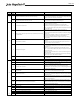


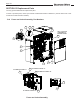


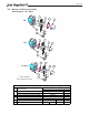


Table Of Contents
- Cover
- TABLE OF CONTENTS
- General Information
- SECTION 2 Venting and Combustion Air
- SECTION 3 Gas supply and Piping
- SECTION 4 Water Flow and Headloss Data
- SECTION 5 Boiler Piping
- SECTION 6 Condensate Drain Trap
- SECTION 7 Electrical Connections
- 7.A Installation Warnings
- 7.B Main Power Connections
- 7.C Main Power Data
- 7.D Control Panel Layout
- 7.E Field Connections
- 7.E.1 Power
- 7.E.2 Dry Contacts
- 7.E.3 Temperature Sensors
- 7.E.4 Safety Chain
- 7.E.5 Isolation Valve
- 7.E.6 Heat Demands
- 7.E.7 Analog In and Analog Out
- 7.E.8 Dry Contacts. Run & Alarm
- 7.E.9 RS 485 for Cascade (Lead Lag)
- 7.E.10 RS485 BMS
- 7.F Modbus to BACnet Memory Map (4 pages)
- 7.G WiringDiagram
- 7.H High Voltage Wiring Diagrams (5 pages)
- 7.I Ladder Diagrams (8 pages)
- SECTION 8 Control Operation
- 8.A The Home Screen
- 8.B Login to Lock / Unlock the Display Screen
- 8.C Quick Start
- 8.D Configuration
- 8.E Service Screens
- 8.E.1 Burner
- 8.E.2 Digital I/O ( Input / Output )
- 8.E.3 Analog I/O
- 8.E.4 Screen Settings Timeout
- 8.E.5 History
- 8.E.6 Restart Touchscreen & Recalibrate
- 8.E.7 Factory Reset
- 8.E.8 HMI Model OEM only
- 8.E.9 BIC Model OEM only
- 8.E.10 Both Model. OEM only.
- 8.E.11 About (the Firmware)
- 8.E.12 O2 (Trim Set Point)
- 8.E.13 LMV
- 8.F Messages and USB
- 8.G Active Demands
- SECTION 9 Parameter Tables (3 pages)
- SECTION 10 Initial startupInstructions
- SECTION 11 Maintenance
- SECTION 12 Troubleshooting
- SECTION 13 Replacement Parts
- 13.A Frame and Jacket Assembly, Part Numbers
- 13.B Control Panel Assembly, Part Numbers
- 13.C Blower and Burner Assembly,Part Numbers. ALL Sizes
- 13.D AC Distribution Box Assemblies and Part Numbers
- 13.E Burner Door Part Numbers
- 13.F Waterway Inlet Assembly, Part Numbers
- 13.G Waterway Outlet Assembly, Part Numbers
- 13.H Gas Train Part Numbers
- 13.I Exhaust Manifold Part Numbers

Page 122
Error
Code
Diag.
Code
Meaning for the LMV3 Corrective Action
Note: Diagnostic codes are additive. If a diagnostic code appears that is not on this list, it is a combination of multiple diagnostic codes.
16 Interruption of speed signal
No speed signal was detected.
1) Ensure that the motor is rotating. If it is not, check the wiring of the
VSD / PWM blower.
2) If using a VSD, turn the motor by hand to ensure that the LED on the
speed sensor lights up when it sees the speed wheel. If it does not,
decrease gap between speed wheel and speed sensor and check the
wiring of the speed sensor. If there are no issues, replace speed sensor.
32 Quick shutdown due to excessive speed deviation
The speed of the motor was more than 10% different than the anticipated
speed for more than 1 second.
1) Check the ramp times of the VSD and LMV3. Increase if necessary.
The ramp times in the LMV3 should be at least 20% longer than the ramp
times in the VSD.
2) Check the setting of parameter 661.
64 VSD speed is below minimum speed (phase dependent)
1) Standby (phase 12): Ensure parameter 669:01 (maximum speed) is set
to a higher value than parameter 669:00 (minimum speed).
2) Standby (phase 12): Ensure parameter 663 (near zone) is set to a
higher value than parameter 662 (neutral zone).
3) Check the absolute speed (parameter 935) to ensure the correct speed
is being detected by the LMV3.
4) Prepurge (phase 30): The detected speed was below the minimum
prepurge speed (parameter 667), or the setting of parameter 503:01 or
506:01 is below the setting of parameter 667.
5) Operation (phases 40-64): The detected speed was below the
minimum operation speed (parameter 669:00), or a VSD curve point was
set below the setting of parameter 669:00.
128 VSD speed exceeds maximum speed (phase dependent)
1) Standby (phase 12): Ensure parameter 226/266/326/366 is set to a
higher value than parameter 665 (time outside near zone).
2) Standby (phase 12): Ensure parameter 669:01 (maximum speed) is set
to a higher value than parameter 669:00 (minimum speed).
3) Standby (phase 12): Ensure parameter 663 (near zone) is set to a
higher value than parameter 662 (neutral zone).
4) Check the absolute speed (parameter 935) to ensure the correct speed
is being detected by the LMV3.
5) Ignition (phase 38): The detected speed was above the maximum
ignition speed (parameter 668), or the VSD speed setting of P0 is above
the setting of parameter 668.
6) Operation (phases 40-64): The detected speed was above the
maximum operation speed (parameter 669:01), or a VSD curve point was
set above the setting of parameter 669:01.
255 Failed forced travel test
If the LMV3 remains at the same fire rate for an extended period of time,
a minimal load change is forced, and the corresponding feedback from
the PWM blower is checked. If this fault occurs, the PWM blower speed
change was insufficient in response to the load change.
Any # Curve slope actuators
1 VSD: Curve too steep in terms of ramp speed
2 Fuel actuator: Curve too steep in terms of ramp rate
4 Air actuator: Curve too steep in terms of ramp rate
Any # Referencing error on actuators
0 Referencing error of fuel actuator
1 Referencing error of air actuator
128 Referencing error due to parameter change
Any # Error fuel actuator
An error occurred pertaining to the fuel actuator. See diagnostic codes
for more information.
84
83
83
All SQM33… actuators must travel outside of their 0-90° operating range
before starting up the burner in order to "reference" their position. This
fault means that the referencing was unsuccessful.
1) Check the setting of parameter 601 (fuel 0) and 608 (fuel 1). Index 00
sets the fuel actuator reference direction and index 01 sets the air
actuator reference direction.
2) Check to make sure the actuators are not binding when trying to
reference (ensure that overstroking below 0° or above 90° is possible).
3) Check the setting of parameter 613 (fuel 0) and 614 (fuel 1) to ensure
the actuator type is set correctly.
4) Make sure that the actuator's are plugged into the correct terminal on
the LMV3.
The difference in position between two adjacent curve points is too large.
See diagnostic code for which actuator / VSD has positions that are too far
apart. For actuators, either increase the setting of parameter 544, or
decrease the distance between curve points. For VSD, either increase the
setting of parameter 544, decrease the setting of parameters 522 and
523, decrease the distance between curve points, or decrease parameter
647.
85