
Installation / Operation Instruction Manual


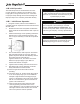
Table Of Contents
- Cover
- TABLE OF CONTENTS
- General Information
- SECTION 2 Venting and Combustion Air
- SECTION 3 Gas supply and Piping
- SECTION 4 Water Flow and Headloss Data
- SECTION 5 Boiler Piping
- SECTION 6 Condensate Drain Trap
- SECTION 7 Electrical Connections
- 7.A Installation Warnings
- 7.B Main Power Connections
- 7.C Main Power Data
- 7.D Control Panel Layout
- 7.E Field Connections
- 7.E.1 Power
- 7.E.2 Dry Contacts
- 7.E.3 Temperature Sensors
- 7.E.4 Safety Chain
- 7.E.5 Isolation Valve
- 7.E.6 Heat Demands
- 7.E.7 Analog In and Analog Out
- 7.E.8 Dry Contacts. Run & Alarm
- 7.E.9 RS 485 for Cascade (Lead Lag)
- 7.E.10 RS485 BMS
- 7.F Modbus to BACnet Memory Map (4 pages)
- 7.G WiringDiagram
- 7.H High Voltage Wiring Diagrams (5 pages)
- 7.I Ladder Diagrams (8 pages)
- SECTION 8 Control Operation
- 8.A The Home Screen
- 8.B Login to Lock / Unlock the Display Screen
- 8.C Quick Start
- 8.D Configuration
- 8.E Service Screens
- 8.E.1 Burner
- 8.E.2 Digital I/O ( Input / Output )
- 8.E.3 Analog I/O
- 8.E.4 Screen Settings Timeout
- 8.E.5 History
- 8.E.6 Restart Touchscreen & Recalibrate
- 8.E.7 Factory Reset
- 8.E.8 HMI Model OEM only
- 8.E.9 BIC Model OEM only
- 8.E.10 Both Model. OEM only.
- 8.E.11 About (the Firmware)
- 8.E.12 O2 (Trim Set Point)
- 8.E.13 LMV
- 8.F Messages and USB
- 8.G Active Demands
- SECTION 9 Parameter Tables (3 pages)
- SECTION 10 Initial startupInstructions
- SECTION 11 Maintenance
- SECTION 12 Troubleshooting
- SECTION 13 Replacement Parts
- 13.A Frame and Jacket Assembly, Part Numbers
- 13.B Control Panel Assembly, Part Numbers
- 13.C Blower and Burner Assembly,Part Numbers. ALL Sizes
- 13.D AC Distribution Box Assemblies and Part Numbers
- 13.E Burner Door Part Numbers
- 13.F Waterway Inlet Assembly, Part Numbers
- 13.G Waterway Outlet Assembly, Part Numbers
- 13.H Gas Train Part Numbers
- 13.I Exhaust Manifold Part Numbers

Page 108
12. Check the gauge for correct water pressure and
also check the water level in the system. If the
height indicated above the boiler ensures that water
is at the highest point in the circulating loop, then
the system is ready for operation.
13. Refer to local codes and the make-up water valve
manufacturer’s instructions as to whether the make-up
water valve should be left open or closed.
14. Press the reset on the low pressure switch.
15. After placing the unit in operation, the ignition
system safety shuto device must be tested.
First, shut o the manual gas valve, and then call
the unit for heat. The main gas terminals will be
energized and attempting to light for ve seconds
and then will de-energize. The unit will go into
lockout after the required number of trials for ignition
periods.
Second, press the manual reset button on the boiler
control, or the user display, open the manual gas
valve and allow the unit to light. While the unit is
operating, close the manual gas valve and ensure
that power to the main gas valve has been cut.
16. Within three (3) days of start up, recheck all air
bleeders and the expansion tank as described
previously in Steps 4 and 8.
NOTE - The installer is responsible for identifying
to the owner/operator the location of all emergency
shuto devices.
WARNING
Do not use this unit if any part has been under water.
Immediately call a qualied service technician to
inspect the unit and to replace any part of the control
system and any gas control that may have been
under water.
SECTION 10 Initial startup
Instructions
10.A Filling the Boiler System
1. Ensure the system is fully connected. Close all
bleeding devices and open the make-up water
valve. Allow the system to ll slowly.
2. If a make-up water pump is employed, adjust the
pressure switch on pumping system to provide a
minimum of 12 psi (81.8 kPa) at the highest point in
the heating loop.
3. If a water pressure regulator is provided on the
make-up water line, adjust the pressure regulator
to provide at least 12 psi (81.8 kPa) at the highest
point in the heating loop.
4. Bleed all air from the heating system by opening
any bleed valves (air eliminators) throughout the
heated system, unless automatic air bleeders are
provided at those points.
5. To remove all air from the heat exchanger, Initial
purging of air from the heat exchanger can be
accomplished by opening the pressure relief valve
using the manual lever.
WARNING
Failure to remove all air from the heat exchanger
could lead to property damage, severe injury or death.
6. Open all strainers in the circulating system, check
the operation of the ow switch (if equipped), and
check for debris. If debris is present, clean out the
strainers to ensure proper circulation.
7. Check the liquid level in the expansion tank. With
the system full of water and under normal operating
pressure, the level of water in the expansion tank
should not exceed ¼ of the total with the balance
lled with air.
8. Start up the boiler following the procedure in this
manual. Operate the entire system, including the
pump, boiler, and radiation units for one hour.
9. Recheck the water level in the expansion tank. If
the water level exceeds ¼ of the volume of the
expansion tank, open the tank drain, and drain to
that level.
10. Shut down the entire system and vent all radiation
units and high points in the system piping, as
described in Step 4.
11. Close the make-up water valve. Check the strainer
in the pressure reducing valve for sediment or
debris from the make-up water line. Reopen the
make-up water valve.