
Installation / Operation Instruction Manual

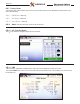

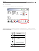


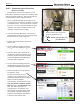
Table Of Contents
- Cover
- TABLE OF CONTENTS
- General Information
- SECTION 2 Venting and Combustion Air
- SECTION 3 Gas supply and Piping
- SECTION 4 Water Flow and Headloss Data
- SECTION 5 Boiler Piping
- SECTION 6 Condensate Drain Trap
- SECTION 7 Electrical Connections
- 7.A Installation Warnings
- 7.B Main Power Connections
- 7.C Main Power Data
- 7.D Control Panel Layout
- 7.E Field Connections
- 7.E.1 Power
- 7.E.2 Dry Contacts
- 7.E.3 Temperature Sensors
- 7.E.4 Safety Chain
- 7.E.5 Isolation Valve
- 7.E.6 Heat Demands
- 7.E.7 Analog In and Analog Out
- 7.E.8 Dry Contacts. Run & Alarm
- 7.E.9 RS 485 for Cascade (Lead Lag)
- 7.E.10 RS485 BMS
- 7.F Modbus to BACnet Memory Map (4 pages)
- 7.G WiringDiagram
- 7.H High Voltage Wiring Diagrams (5 pages)
- 7.I Ladder Diagrams (8 pages)
- SECTION 8 Control Operation
- 8.A The Home Screen
- 8.B Login to Lock / Unlock the Display Screen
- 8.C Quick Start
- 8.D Configuration
- 8.E Service Screens
- 8.E.1 Burner
- 8.E.2 Digital I/O ( Input / Output )
- 8.E.3 Analog I/O
- 8.E.4 Screen Settings Timeout
- 8.E.5 History
- 8.E.6 Restart Touchscreen & Recalibrate
- 8.E.7 Factory Reset
- 8.E.8 HMI Model OEM only
- 8.E.9 BIC Model OEM only
- 8.E.10 Both Model. OEM only.
- 8.E.11 About (the Firmware)
- 8.E.12 O2 (Trim Set Point)
- 8.E.13 LMV
- 8.F Messages and USB
- 8.G Active Demands
- SECTION 9 Parameter Tables (3 pages)
- SECTION 10 Initial startupInstructions
- SECTION 11 Maintenance
- SECTION 12 Troubleshooting
- SECTION 13 Replacement Parts
- 13.A Frame and Jacket Assembly, Part Numbers
- 13.B Control Panel Assembly, Part Numbers
- 13.C Blower and Burner Assembly,Part Numbers. ALL Sizes
- 13.D AC Distribution Box Assemblies and Part Numbers
- 13.E Burner Door Part Numbers
- 13.F Waterway Inlet Assembly, Part Numbers
- 13.G Waterway Outlet Assembly, Part Numbers
- 13.H Gas Train Part Numbers
- 13.I Exhaust Manifold Part Numbers

Page 103
Messages
8.F.2 USB Functionality
Figure 42. Photo of USB Slot on
the back of touchscreen
display.
When the USB icon has appeared over the Message icon, press the USB
icon to access the USB menu. The following three tasks will be available:
• Download Parameters from the boiler: During a cascade setup or
a control replacement, enter the values in one unit, to copy into the
others.
• Upload Parameters from the boiler: Uploads all parameters and
settings into a thumb drive for documentation purposes, or copies these
settings from unit to unit.
•
Upload Data from the boiler: This is used to retrieve run-time data,
and history. It captures all settings in a tab delimited text le, for use with
spreadsheet programs.
8.F Messages and USB
8.F.1 Messages
The ‘Messages’ icon at the bottom of the home screen
displays an ‘Exclamation Point’ when messages are present.
Press the icon to see the message(s).
The USB port is on the back of the display. To access it, open
both panels and look for the black USB cable extending from the
back of the display. See Figure 42.