
Installation / Operation Instruction Manual
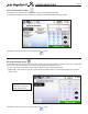
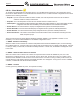
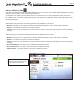
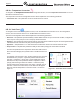

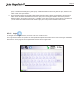
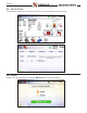
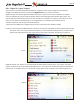
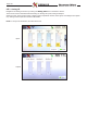
Table Of Contents
- Cover
- TABLE OF CONTENTS
- General Information
- SECTION 2 Venting and Combustion Air
- SECTION 3 Gas supply and Piping
- SECTION 4 Water Flow and Headloss Data
- SECTION 5 Boiler Piping
- SECTION 6 Condensate Drain Trap
- SECTION 7 Electrical Connections
- 7.A Installation Warnings
- 7.B Main Power Connections
- 7.C Main Power Data
- 7.D Control Panel Layout
- 7.E Field Connections
- 7.E.1 Power
- 7.E.2 Dry Contacts
- 7.E.3 Temperature Sensors
- 7.E.4 Safety Chain
- 7.E.5 Isolation Valve
- 7.E.6 Heat Demands
- 7.E.7 Analog In and Analog Out
- 7.E.8 Dry Contacts. Run & Alarm
- 7.E.9 RS 485 for Cascade (Lead Lag)
- 7.E.10 RS485 BMS
- 7.F Modbus to BACnet Memory Map (4 pages)
- 7.G WiringDiagram
- 7.H High Voltage Wiring Diagrams (5 pages)
- 7.I Ladder Diagrams (8 pages)
- SECTION 8 Control Operation
- 8.A The Home Screen
- 8.B Login to Lock / Unlock the Display Screen
- 8.C Quick Start
- 8.D Configuration
- 8.E Service Screens
- 8.E.1 Burner
- 8.E.2 Digital I/O ( Input / Output )
- 8.E.3 Analog I/O
- 8.E.4 Screen Settings Timeout
- 8.E.5 History
- 8.E.6 Restart Touchscreen & Recalibrate
- 8.E.7 Factory Reset
- 8.E.8 HMI Model OEM only
- 8.E.9 BIC Model OEM only
- 8.E.10 Both Model. OEM only.
- 8.E.11 About (the Firmware)
- 8.E.12 O2 (Trim Set Point)
- 8.E.13 LMV
- 8.F Messages and USB
- 8.G Active Demands
- SECTION 9 Parameter Tables (3 pages)
- SECTION 10 Initial startupInstructions
- SECTION 11 Maintenance
- SECTION 12 Troubleshooting
- SECTION 13 Replacement Parts
- 13.A Frame and Jacket Assembly, Part Numbers
- 13.B Control Panel Assembly, Part Numbers
- 13.C Blower and Burner Assembly,Part Numbers. ALL Sizes
- 13.D AC Distribution Box Assemblies and Part Numbers
- 13.E Burner Door Part Numbers
- 13.F Waterway Inlet Assembly, Part Numbers
- 13.G Waterway Outlet Assembly, Part Numbers
- 13.H Gas Train Part Numbers
- 13.I Exhaust Manifold Part Numbers

Page 94
CONFIGURATION
8.D.10.e Temperature Conversion
To navigate to the Temperature Conversion Conguration Screen, touch the Temperature Conversion Icon on the
Miscellaneous Features screen.
The Temperature Conversion Conguration Screen allows adjustment of the following parameter:
• Conversion unit – This parameter can be set to Fahrenheit or Celsius.
8.D.10.f Anti-Frost
To navigate to the Anti-Frost Conguration Screen, touch the Miscellaneous Features Icon on the Conguration
Screen, then touch the Anti-Frost Icon on the Miscellaneous Features screen.
The Anti-Frost Conguration Screen allows adjustment of the following parameters:
• Anti-Frost – This parameter provides the ability to either disable anti-frost or upon an anti-frost condition, congure the
unit to only turn on the pump or to turn on the pump and re the burner.
• Set Point – The unit will enter anti-frost mode when the unit’s inlet sensor reads the set point minus the hysteresis value.
It will leave anti-frost mode at the set point plus the hysteresis value.
• Hysteresis – This parameter is a +/- oset of the Anti-Frost Set Point used to turn on/o the Anti-Frost mode.
• Pump Control – This parameter provides the ability to select which pump(s) are used in Anti-Frost Mode.
The Set Point parameter is the temperature at the boiler inlet sensor to
which the boiler will apply the Hysteresis value to enable the Anti-Frost
mode.
For example, if the Set Point is 44°F, and the Hysteresis is 4, Anti-Frost
will initiate at 40°F (set point – hysteresis) and then will end at 48°F
(set point + hysteresis). If Pump Only or Pump and Burner mode is
selected, the Pump Control parameter allows conguration of which
pump(s) will run during an anti-frost condition. At least one pump
must be selected, but all three pumps (unit, DHW, or System) can be
selected. If Anti-Frost mode is active, a snow ake icon will appear
above the unit inlet temperature on the home screen. As shown in
Figure 41
Figure 41. Active Anti Frost Condition