
Installation / Operation Instruction Manual
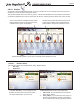
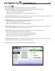
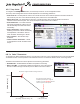
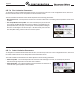
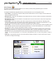
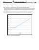

Table Of Contents
- Cover
- TABLE OF CONTENTS
- General Information
- SECTION 2 Venting and Combustion Air
- SECTION 3 Gas supply and Piping
- SECTION 4 Water Flow and Headloss Data
- SECTION 5 Boiler Piping
- SECTION 6 Condensate Drain Trap
- SECTION 7 Electrical Connections
- 7.A Installation Warnings
- 7.B Main Power Connections
- 7.C Main Power Data
- 7.D Control Panel Layout
- 7.E Field Connections
- 7.E.1 Power
- 7.E.2 Dry Contacts
- 7.E.3 Temperature Sensors
- 7.E.4 Safety Chain
- 7.E.5 Isolation Valve
- 7.E.6 Heat Demands
- 7.E.7 Analog In and Analog Out
- 7.E.8 Dry Contacts. Run & Alarm
- 7.E.9 RS 485 for Cascade (Lead Lag)
- 7.E.10 RS485 BMS
- 7.F Modbus to BACnet Memory Map (4 pages)
- 7.G WiringDiagram
- 7.H High Voltage Wiring Diagrams (5 pages)
- 7.I Ladder Diagrams (8 pages)
- SECTION 8 Control Operation
- 8.A The Home Screen
- 8.B Login to Lock / Unlock the Display Screen
- 8.C Quick Start
- 8.D Configuration
- 8.E Service Screens
- 8.E.1 Burner
- 8.E.2 Digital I/O ( Input / Output )
- 8.E.3 Analog I/O
- 8.E.4 Screen Settings Timeout
- 8.E.5 History
- 8.E.6 Restart Touchscreen & Recalibrate
- 8.E.7 Factory Reset
- 8.E.8 HMI Model OEM only
- 8.E.9 BIC Model OEM only
- 8.E.10 Both Model. OEM only.
- 8.E.11 About (the Firmware)
- 8.E.12 O2 (Trim Set Point)
- 8.E.13 LMV
- 8.F Messages and USB
- 8.G Active Demands
- SECTION 9 Parameter Tables (3 pages)
- SECTION 10 Initial startupInstructions
- SECTION 11 Maintenance
- SECTION 12 Troubleshooting
- SECTION 13 Replacement Parts
- 13.A Frame and Jacket Assembly, Part Numbers
- 13.B Control Panel Assembly, Part Numbers
- 13.C Blower and Burner Assembly,Part Numbers. ALL Sizes
- 13.D AC Distribution Box Assemblies and Part Numbers
- 13.E Burner Door Part Numbers
- 13.F Waterway Inlet Assembly, Part Numbers
- 13.G Waterway Outlet Assembly, Part Numbers
- 13.H Gas Train Part Numbers
- 13.I Exhaust Manifold Part Numbers

Page 87
8.D.8 External
The External Conguration Screen applies to the 0-10VDC (4-20mA) analog input BAS signal, and allows
adjustment of the following parameters:
To navigate to the External Conguration Screen, touch the External Icon on the Conguration Screen.
•
Control Mode – This parameter provides the ability to either disable external control or congure the unit for Boiler Set
Point or Firing Rate control mode.
•
Max Set Point – When the Control Mode is set to Boiler Set Point, this is the maximum value that corresponds to
the Demand Max value.
•
Min Set Point – When the Control Mode is set to Boiler Set Point, this is the minimum value that corresponds to
the Demand Min value.
•
Demand Max – This is the maximum value that corresponds to the control mode selected. With Firing Rate
control mode selected, this is the maximum rate at which the boiler will run. The unit of this parameter is %, so if
the value of this parameter is 10000, or 100.00%, this equates to 10.0VDC or 20mA.
•
Demand Min – This is the minimum value that corresponds to the control mode selected. With Firing Rate control
mode selected, this is
the minimum rate at which the boiler will run. The unit of this parameter is %, so if the value of
this parameter is 2000, or 20.00%, this equates to 2.0VDC or 4.8mA.
•
Demand On – This is the threshold (VDC/mA) at which the input signal will initiate the selected control mode behavior.
The unit of this parameter is %, so if the value of this parameter is 1500, or 15.00%, this equates to 1.5VDC or 4.6mA.
•
Demand O – This is the threshold (VDC/mA) at which the input signal will deactivate the selected control mode
behavior. The unit of this parameter is %, so if the value of this parameter is 1000, or 10.00%, this equates to 1.0VDC or
4.4mA.
•
Input Type – This parameter allows the user to select between voltage (0-10VDC) or current (4-20mA) input. Jumpers
will need to be congured accordingly.
CONFIGURATION