
Installation / Operation Instruction Manual
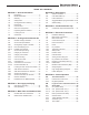
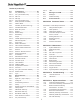
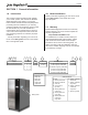
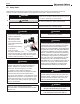
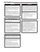
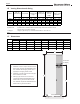
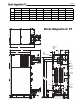
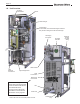
Table Of Contents
- Cover
- TABLE OF CONTENTS
- General Information
- SECTION 2 Venting and Combustion Air
- SECTION 3 Gas supply and Piping
- SECTION 4 Water Flow and Headloss Data
- SECTION 5 Boiler Piping
- SECTION 6 Condensate Drain Trap
- SECTION 7 Electrical Connections
- 7.A Installation Warnings
- 7.B Main Power Connections
- 7.C Main Power Data
- 7.D Control Panel Layout
- 7.E Field Connections
- 7.E.1 Power
- 7.E.2 Dry Contacts
- 7.E.3 Temperature Sensors
- 7.E.4 Safety Chain
- 7.E.5 Isolation Valve
- 7.E.6 Heat Demands
- 7.E.7 Analog In and Analog Out
- 7.E.8 Dry Contacts. Run & Alarm
- 7.E.9 RS 485 for Cascade (Lead Lag)
- 7.E.10 RS485 BMS
- 7.F Modbus to BACnet Memory Map (4 pages)
- 7.G WiringDiagram
- 7.H High Voltage Wiring Diagrams (5 pages)
- 7.I Ladder Diagrams (8 pages)
- SECTION 8 Control Operation
- 8.A The Home Screen
- 8.B Login to Lock / Unlock the Display Screen
- 8.C Quick Start
- 8.D Configuration
- 8.E Service Screens
- 8.E.1 Burner
- 8.E.2 Digital I/O ( Input / Output )
- 8.E.3 Analog I/O
- 8.E.4 Screen Settings Timeout
- 8.E.5 History
- 8.E.6 Restart Touchscreen & Recalibrate
- 8.E.7 Factory Reset
- 8.E.8 HMI Model OEM only
- 8.E.9 BIC Model OEM only
- 8.E.10 Both Model. OEM only.
- 8.E.11 About (the Firmware)
- 8.E.12 O2 (Trim Set Point)
- 8.E.13 LMV
- 8.F Messages and USB
- 8.G Active Demands
- SECTION 9 Parameter Tables (3 pages)
- SECTION 10 Initial startupInstructions
- SECTION 11 Maintenance
- SECTION 12 Troubleshooting
- SECTION 13 Replacement Parts
- 13.A Frame and Jacket Assembly, Part Numbers
- 13.B Control Panel Assembly, Part Numbers
- 13.C Blower and Burner Assembly,Part Numbers. ALL Sizes
- 13.D AC Distribution Box Assemblies and Part Numbers
- 13.E Burner Door Part Numbers
- 13.F Waterway Inlet Assembly, Part Numbers
- 13.G Waterway Outlet Assembly, Part Numbers
- 13.H Gas Train Part Numbers
- 13.I Exhaust Manifold Part Numbers

Page 8
Venting
Information
inches cm inches cm ft* m inches cm ft* m inches cm
1000 6 15 6 15 100 30.5 6 15 100 30.5 12 30
1500 8 20 8 20 100 30.5 8 20 100 30.5 14 36
2000 8 20 8 20 100 30.5 8 20 100 30.5 18 46
3000 10 25 10 25 100 30.5 10 25 100 30.5 22 56
*Equivalent Feet: Equivalent Feet: To calculate maximum equivalent length, measure the linear feet of the pipe
and add 5 feet (1.5m) for each elbow used.
***Category II: Category II pipe size may vary. Draft must remain between -0.1 and -0.001" w.c..
Notes:
1. Installations in the U.S. require exhaust vent pipe that is CPVC complying with ANSI/ASTM D1785 F441,
stainless steel complying with UL1738, or polypropylene complying with ULC S636.
2. Installations in Canada require exhaust vent pipe that is certified to ULC S636.
3. Intake (air) pipe must be PVC or CPVC that complies with ANSI/ASTM D1785 F441, ABS that complies with
ANSI/ASTM D1527, stainless steel, or galvanized material.
Vent / Air
Connector Size
Model
Maximum
Ducted Air Pipe
Length
Air Pipe Size
Typical
Category II Vent
Pipe Size***
Maximum
Category IV
Vent Pipe
Length
Category IV
Vent Pipe Size
NOTES:
1. Installations in the U.S. require exhaust vent pipe
that is CPVC complying with ANSI/ASTM D1785
F441, stainless steel complying with UL1738, or
polypropylene complying with ULC S636.
2. Installations in Canada require exhaust vent pipe
that is certied to ULC S636.
3. Intake (air) pipe must be PVC or CPVC that
complies with ANSI/ASTM ANSI/ASTM D1527,
stainless steel, or galvanized material. D1785
F441, ABS that complies with ANSI/ASTM D1527,
stainless steel, or galvanized material.
1.E Venting Dimensions & Sizing
Table 1. Vent Sizing
Table 2. Dimensions
Dimensions
Model
in (cm) in (cm) in (cm) in (cm) in (cm) in (cm) in (cm) in (cm)
1000 30.2 (76.7) 80.0 (203) 52.4 (133) 70.5 (179) 60.0 (152) 8.2 (20.9) 60.0 (152) 74.2 (188)
1500 30.2 (76.7) 80.0 (203) 52.4 (133) 70.5 (179) 60.0 (152) 7.8 (19.7) 60.3 (153) 74.2 (188)
2000 34.6 (87.9) 80.0 (203) 56.3 (143) 73.3 (189) 60.0 (152) 9.1 (23.0) 63.1 (160) 73.6 (187)
3000 34.6 (87.9) 80.0 (203) 56.3 (143) 75.5 (192) 60.0 (152) 8.4 (21.4) 65.4 (166) 73.6 (187)
Model
in (cm) in (cm) in (cm) in (cm) in (cm) in (cm) in (cm) in (cm)
1000 70.8 (180) 67.3 (171) 13.4 (34.0) 13.0 (33.1) 7.9 (20) 15.1 (38.4) 6.4 (16.3) 2.9 (7.3)
1500 70.8 (180) 67.3 (171) 13.4 (34.0) 13.0 (33.1) 7.9 (20) 15.1 (38.4) 6.4 (16.3) 2.7 (6.9)
2000 72.0 (183) 67.3 (171) 13.4 (34.0) 13.0 (33.1) 10.1 (26) 17.3 (44.0) 8.2 (20.9) 3.8 (9.5)
3000 72.0 (183) 68.4 (174) 14.4 (36.6) 14.0 (35.5) 10.1 (26) 17.3 (44.0) 8.2 (20.9) 3.6 (9.1)
Inlet and outlet water connections are 3-inch 150# flanges, 4 hole, 6" bolt circle
"K""J"
"H""G""F""E""D""C""B""A"
"R""P""N""M""L" "S"
1.F Dimensions
MAGNATHERM FT - Dimensional Data
Touchscreen
Display
B
A
E
Pressure
Inlet
Condensate Trap
1" Drain Hose
Air
Valve
Relief
Inlet
3” Flange
3” Flange
Water
Outlet
Water
Vent
Boxes
Electrical
2" NPT Pipe
Gas
Inlet
R
S
P
H
J
K
L
N
M
F
G
D
C
MODEL A B C D E F G H J K L M N P
)4.251(/0.06)9.02(/2.80.1
))3.351(/3.06)7.91(/8.75.1
)2.061(/1.36)0.32(/1.9)8.881(/3.370.2
)5.53(/0.41)6.63(/4.41)6.371(/4.86)2.661(/4.56)4.12(/4.8)8.191(/5.570.3
CFT Dimensional Data (inches/(cm)
)7.971(/8.07)4.881(/2.47)331(/4.25
67.3/(171.1)
60.0/(152.4)
17.3/(44.0)34.6/(87.9) 56.3/(143.1)
70.5/(179)30.2/(76.7)
80.0/(203.2)
13.4/(34) 13.0/(33.1)
73.6/(186.8) 72.0/(182.8)
3.8/(9.6)
15.1/(38.4)
R S
2.9/(7.3)
2.7/(6.9)
3.8/(9.5)
3.6/(9.1)
8.2/(20.9)
6.4/(16.3)
3” Max
4” Min
Figure 1. Dimensions