
Installation / Operation Instruction Manual
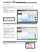
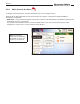
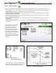
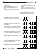
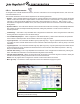
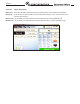
Table Of Contents
- Cover
- TABLE OF CONTENTS
- General Information
- SECTION 2 Venting and Combustion Air
- SECTION 3 Gas supply and Piping
- SECTION 4 Water Flow and Headloss Data
- SECTION 5 Boiler Piping
- SECTION 6 Condensate Drain Trap
- SECTION 7 Electrical Connections
- 7.A Installation Warnings
- 7.B Main Power Connections
- 7.C Main Power Data
- 7.D Control Panel Layout
- 7.E Field Connections
- 7.E.1 Power
- 7.E.2 Dry Contacts
- 7.E.3 Temperature Sensors
- 7.E.4 Safety Chain
- 7.E.5 Isolation Valve
- 7.E.6 Heat Demands
- 7.E.7 Analog In and Analog Out
- 7.E.8 Dry Contacts. Run & Alarm
- 7.E.9 RS 485 for Cascade (Lead Lag)
- 7.E.10 RS485 BMS
- 7.F Modbus to BACnet Memory Map (4 pages)
- 7.G WiringDiagram
- 7.H High Voltage Wiring Diagrams (5 pages)
- 7.I Ladder Diagrams (8 pages)
- SECTION 8 Control Operation
- 8.A The Home Screen
- 8.B Login to Lock / Unlock the Display Screen
- 8.C Quick Start
- 8.D Configuration
- 8.E Service Screens
- 8.E.1 Burner
- 8.E.2 Digital I/O ( Input / Output )
- 8.E.3 Analog I/O
- 8.E.4 Screen Settings Timeout
- 8.E.5 History
- 8.E.6 Restart Touchscreen & Recalibrate
- 8.E.7 Factory Reset
- 8.E.8 HMI Model OEM only
- 8.E.9 BIC Model OEM only
- 8.E.10 Both Model. OEM only.
- 8.E.11 About (the Firmware)
- 8.E.12 O2 (Trim Set Point)
- 8.E.13 LMV
- 8.F Messages and USB
- 8.G Active Demands
- SECTION 9 Parameter Tables (3 pages)
- SECTION 10 Initial startupInstructions
- SECTION 11 Maintenance
- SECTION 12 Troubleshooting
- SECTION 13 Replacement Parts
- 13.A Frame and Jacket Assembly, Part Numbers
- 13.B Control Panel Assembly, Part Numbers
- 13.C Blower and Burner Assembly,Part Numbers. ALL Sizes
- 13.D AC Distribution Box Assemblies and Part Numbers
- 13.E Burner Door Part Numbers
- 13.F Waterway Inlet Assembly, Part Numbers
- 13.G Waterway Outlet Assembly, Part Numbers
- 13.H Gas Train Part Numbers
- 13.I Exhaust Manifold Part Numbers

Page 74
8.D.4 Cascade (All about Lead / Lag)
An installation with two or more units may be congured for cascade operation. Up to eight units can be
cascaded and controlled together.
To navigate to the Cascade Screen, touch the Cascade Icon on the Conguration Screen.
The Cascade Screen provides four navigation icons to congure the system for cascade operations. These
navigation icons are:
•
Cascade – This icon navigates to the Cascade Parameters screen for hydronic boiler cascade operations. This
icon is available on hydronic boilers (MGH) only.
•
Rotation – This icon navigates to the cascade rotation screen.
•
Redundancy – This icon navigates to the setup screen for cascade leader redundancy options.
About Cascading (Lead / Lag)
The Lead boiler uses the Base Load Value to determine when to re the Lag units
and at what ring rate. The Base Load Value should be adjusted based on the
number of units installed, with a default value of 65%. Recommended base load
values based on the number of units installed is shown in the table below. The
Base Load Value is adjustable via the DU with installer login credentials.
Upon an active cascade heat demand, the Lead boiler will dictate which unit will
re rst based on the cascade rotation logic. As the ring rate of this unit reaches
the Base Load Value, once the Min On Time timer expires, the next unit in the
sequence will re and both units will modulate up or down together at the same
ring rate in reaction to changes in heat demand. This pattern will continue until
the ring rates of all cascaded units reach the base load value. Once all units are
ring at the base load value, the ring rate can exceed the base load value, with
all units maintaining the same ring rate. Refer to the Lead / Lag gures below for
additional clarication.
With boilers ring at the same ring rate, minimum ring rates need to be taken
into consideration. Units with varying turndown ratios can be cascaded together,
therefore, the unit with the highest minimum ring rate dictates the minimum ring
rate of the total cascaded system. For example, if a 5:1 unit is cascaded with a
20:1 unit, and the 5:1 unit has reached the base load value, the 20:1 will be called
to run. The 20:1 will re at the same ring rate as the 5:1, which is limited to 20%
Boiler Qty Recommended
Base Load
1 N/A
2 65%
3 50%
4 40%
5 40%
6 40%
7 40%
8 40%
NOTE: A system supply sensor
(supplied with each unit) must be
installed and connected to the
Lead boiler. The Lead boiler will
use this system supply sensor as
the temperature control sensor for
cascade operations.
Table 18. Recommended
Base Load Values