
Installation / Operation Instruction Manual
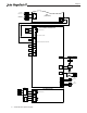
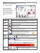

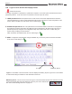
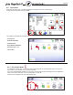
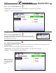

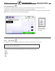

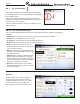
Table Of Contents
- Cover
- TABLE OF CONTENTS
- General Information
- SECTION 2 Venting and Combustion Air
- SECTION 3 Gas supply and Piping
- SECTION 4 Water Flow and Headloss Data
- SECTION 5 Boiler Piping
- SECTION 6 Condensate Drain Trap
- SECTION 7 Electrical Connections
- 7.A Installation Warnings
- 7.B Main Power Connections
- 7.C Main Power Data
- 7.D Control Panel Layout
- 7.E Field Connections
- 7.E.1 Power
- 7.E.2 Dry Contacts
- 7.E.3 Temperature Sensors
- 7.E.4 Safety Chain
- 7.E.5 Isolation Valve
- 7.E.6 Heat Demands
- 7.E.7 Analog In and Analog Out
- 7.E.8 Dry Contacts. Run & Alarm
- 7.E.9 RS 485 for Cascade (Lead Lag)
- 7.E.10 RS485 BMS
- 7.F Modbus to BACnet Memory Map (4 pages)
- 7.G WiringDiagram
- 7.H High Voltage Wiring Diagrams (5 pages)
- 7.I Ladder Diagrams (8 pages)
- SECTION 8 Control Operation
- 8.A The Home Screen
- 8.B Login to Lock / Unlock the Display Screen
- 8.C Quick Start
- 8.D Configuration
- 8.E Service Screens
- 8.E.1 Burner
- 8.E.2 Digital I/O ( Input / Output )
- 8.E.3 Analog I/O
- 8.E.4 Screen Settings Timeout
- 8.E.5 History
- 8.E.6 Restart Touchscreen & Recalibrate
- 8.E.7 Factory Reset
- 8.E.8 HMI Model OEM only
- 8.E.9 BIC Model OEM only
- 8.E.10 Both Model. OEM only.
- 8.E.11 About (the Firmware)
- 8.E.12 O2 (Trim Set Point)
- 8.E.13 LMV
- 8.F Messages and USB
- 8.G Active Demands
- SECTION 9 Parameter Tables (3 pages)
- SECTION 10 Initial startupInstructions
- SECTION 11 Maintenance
- SECTION 12 Troubleshooting
- SECTION 13 Replacement Parts
- 13.A Frame and Jacket Assembly, Part Numbers
- 13.B Control Panel Assembly, Part Numbers
- 13.C Blower and Burner Assembly,Part Numbers. ALL Sizes
- 13.D AC Distribution Box Assemblies and Part Numbers
- 13.E Burner Door Part Numbers
- 13.F Waterway Inlet Assembly, Part Numbers
- 13.G Waterway Outlet Assembly, Part Numbers
- 13.H Gas Train Part Numbers
- 13.I Exhaust Manifold Part Numbers

Page 70
8.D.1 CH (Central Heat)
“CH” stands for “Central Heat.” It is used for space heating demands.
On the Congure Screen, touch the CH thermometer icon to navigate to
the CH Selection Screen
There are two identical heat demands, CH1 and CH2, each with
independent control algorithms and independent inputs on the input
terminal strip, see 7.E.6 on page 42
From the CH Selection Screen, touching CH1 navigates to the CH1
Parameters Menu.
CONFIGURATION
8.D.1.a CH1 (Central Heat, One)
CH1 is one of the heat demands available. The CH1 Conguration Screen allows adjustment of the following
parameters:
•
Ena ble/Disable - This allows CH1 to be enabled or disabled. The default setting is Enabled.
•
Set Point - This is the temperature set point for CH1.
•
On Hysteresis - The temperature at which the hysteresis will turn on.
•
O Hysteresis - The temperature at which the hysteresis will turn o.
•
PID Low - controls the ring rate whenever the
temperature is below the set point. Lower values in
P and I will reduce overshoot.
•
PID High - controls the ring rate between the set
point and the o Hysteresis. Higher values in P and
I will reduce overshoot.
• Output
Freeze - changes the allowable variance
between actual and target ring rate. The larger
the percentage the faster the system can respond
however overshoot can increase too, depending on
the system. (Not available in Cascade)
•
Max Power - allows the user to set a max BTU
output less than the boilers full output. Used when
small loads are applied.
Set Point
On the Set Point screen, use the keypad on
the right or the up/down arrows to enter the
desired temperature set point for CH1. Press
the “Enter” button to save the setting. Set
Point range is 40-210°F, and default is 180°F.