
Installation / Operation Instruction Manual
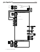
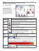

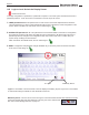
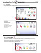
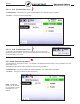

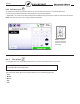

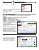
Table Of Contents
- Cover
- TABLE OF CONTENTS
- General Information
- SECTION 2 Venting and Combustion Air
- SECTION 3 Gas supply and Piping
- SECTION 4 Water Flow and Headloss Data
- SECTION 5 Boiler Piping
- SECTION 6 Condensate Drain Trap
- SECTION 7 Electrical Connections
- 7.A Installation Warnings
- 7.B Main Power Connections
- 7.C Main Power Data
- 7.D Control Panel Layout
- 7.E Field Connections
- 7.E.1 Power
- 7.E.2 Dry Contacts
- 7.E.3 Temperature Sensors
- 7.E.4 Safety Chain
- 7.E.5 Isolation Valve
- 7.E.6 Heat Demands
- 7.E.7 Analog In and Analog Out
- 7.E.8 Dry Contacts. Run & Alarm
- 7.E.9 RS 485 for Cascade (Lead Lag)
- 7.E.10 RS485 BMS
- 7.F Modbus to BACnet Memory Map (4 pages)
- 7.G WiringDiagram
- 7.H High Voltage Wiring Diagrams (5 pages)
- 7.I Ladder Diagrams (8 pages)
- SECTION 8 Control Operation
- 8.A The Home Screen
- 8.B Login to Lock / Unlock the Display Screen
- 8.C Quick Start
- 8.D Configuration
- 8.E Service Screens
- 8.E.1 Burner
- 8.E.2 Digital I/O ( Input / Output )
- 8.E.3 Analog I/O
- 8.E.4 Screen Settings Timeout
- 8.E.5 History
- 8.E.6 Restart Touchscreen & Recalibrate
- 8.E.7 Factory Reset
- 8.E.8 HMI Model OEM only
- 8.E.9 BIC Model OEM only
- 8.E.10 Both Model. OEM only.
- 8.E.11 About (the Firmware)
- 8.E.12 O2 (Trim Set Point)
- 8.E.13 LMV
- 8.F Messages and USB
- 8.G Active Demands
- SECTION 9 Parameter Tables (3 pages)
- SECTION 10 Initial startupInstructions
- SECTION 11 Maintenance
- SECTION 12 Troubleshooting
- SECTION 13 Replacement Parts
- 13.A Frame and Jacket Assembly, Part Numbers
- 13.B Control Panel Assembly, Part Numbers
- 13.C Blower and Burner Assembly,Part Numbers. ALL Sizes
- 13.D AC Distribution Box Assemblies and Part Numbers
- 13.E Burner Door Part Numbers
- 13.F Waterway Inlet Assembly, Part Numbers
- 13.G Waterway Outlet Assembly, Part Numbers
- 13.H Gas Train Part Numbers
- 13.I Exhaust Manifold Part Numbers

Page 64
8.B Login to Lock / Unlock the Display Screen
Password Protection:
To change conguration or parameters, a password is required. The control system includes three levels of
password protection. Touch the 'Current Lock Status' icon at the top of the screen.
1- USER password is lhs. This password is for ‘Safe’ access ‘Non-Critical’ adjustments and functions.
Use this password if you want to make adjustments without fear of altering the critical conguration of the
system. When unlocked in the User mode, the icon will change to
2- INSTALLER password is 17. This password is for the trained Installer / Technician for conguration
and parameter changes made during the initial setup and commissioning. Be aware that in this level of
password protection, changes to the conguration setup may result in lock-outs or conicts with your
system setup, resulting in technical issues.
When unlocked in the Installer mode, the icon will change to
3- OEM: Conguration and parameter changes available only to the factory. When unlocked in the OEM
mode, the icon will change to
To Logout
Walk Away Result
Logout. If the Installer is done and wants to lock the display immediately, tap the Logout icon to exit Installer
or User Mode. Exiting the Installer or User Mode will lock the unit.
Walk-Away Result. The user can choose how long the control will remain unlocked after interaction with the
control has stopped. After this time (default is 5 minutes), the screen will lock itself.
See “8.E.4 Screen Settings Timeout” on page 101