
Installation / Operation Instruction Manual
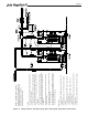
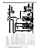

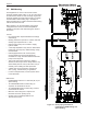

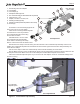
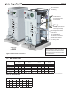
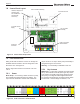
Table Of Contents
- Cover
- TABLE OF CONTENTS
- General Information
- SECTION 2 Venting and Combustion Air
- SECTION 3 Gas supply and Piping
- SECTION 4 Water Flow and Headloss Data
- SECTION 5 Boiler Piping
- SECTION 6 Condensate Drain Trap
- SECTION 7 Electrical Connections
- 7.A Installation Warnings
- 7.B Main Power Connections
- 7.C Main Power Data
- 7.D Control Panel Layout
- 7.E Field Connections
- 7.E.1 Power
- 7.E.2 Dry Contacts
- 7.E.3 Temperature Sensors
- 7.E.4 Safety Chain
- 7.E.5 Isolation Valve
- 7.E.6 Heat Demands
- 7.E.7 Analog In and Analog Out
- 7.E.8 Dry Contacts. Run & Alarm
- 7.E.9 RS 485 for Cascade (Lead Lag)
- 7.E.10 RS485 BMS
- 7.F Modbus to BACnet Memory Map (4 pages)
- 7.G WiringDiagram
- 7.H High Voltage Wiring Diagrams (5 pages)
- 7.I Ladder Diagrams (8 pages)
- SECTION 8 Control Operation
- 8.A The Home Screen
- 8.B Login to Lock / Unlock the Display Screen
- 8.C Quick Start
- 8.D Configuration
- 8.E Service Screens
- 8.E.1 Burner
- 8.E.2 Digital I/O ( Input / Output )
- 8.E.3 Analog I/O
- 8.E.4 Screen Settings Timeout
- 8.E.5 History
- 8.E.6 Restart Touchscreen & Recalibrate
- 8.E.7 Factory Reset
- 8.E.8 HMI Model OEM only
- 8.E.9 BIC Model OEM only
- 8.E.10 Both Model. OEM only.
- 8.E.11 About (the Firmware)
- 8.E.12 O2 (Trim Set Point)
- 8.E.13 LMV
- 8.F Messages and USB
- 8.G Active Demands
- SECTION 9 Parameter Tables (3 pages)
- SECTION 10 Initial startupInstructions
- SECTION 11 Maintenance
- SECTION 12 Troubleshooting
- SECTION 13 Replacement Parts
- 13.A Frame and Jacket Assembly, Part Numbers
- 13.B Control Panel Assembly, Part Numbers
- 13.C Blower and Burner Assembly,Part Numbers. ALL Sizes
- 13.D AC Distribution Box Assemblies and Part Numbers
- 13.E Burner Door Part Numbers
- 13.F Waterway Inlet Assembly, Part Numbers
- 13.G Waterway Outlet Assembly, Part Numbers
- 13.H Gas Train Part Numbers
- 13.I Exhaust Manifold Part Numbers

Page 37
Figure 17. Condensation Trap Assembly
800.900.9276 • Fax 800.559.1583 (Customer Service, Service Advisors)
20 Industrial Way, Rochester, NH 03867 • 603.335.6300 • Fax 603.335.3355 (Applications Engineering)
1869 Sismet Road, Mississauga, Ontario, Canada L4W 1W8 • 905.238.0100 • Fax 905.366.0130
www.Laars.com
Document 4378
Commercial FT, Condensate Trap Assembly Instructions
H2409900-
Page 1 of 1
1. The discharge hose 'end adapter'.
2. Hose adapter.
3. Hose clamps (3).
4. Transparent discharge hose.
5. The condensate trap (pre-assembled with cap & oat).
6. Inlet Hose, 2.5" x .75".
7. Adapter, .75" barb x 1.0" NPT, PVC.
8. Mounting bracket (top half).
9. Mounting bracket (bottom half) with the velcro strap.
10. Screws (2).
NPT discharge
pipe on boiler
Kit Components
The mounting brackets overlap and are
fastened to the unit at existing holes.
Thread item 7 onto the discharge pipe at the
back of the unit. Do not over tighten.
Place the two mounting brackets together
and fasten them to the unit just below
the condensate discharge hose using
the 2 screws as shown.
Assemble items 1 thru 6 to make
the condensate trap sub-assembly.
There will be a remaining hose clamp.
Place it over the inlet hose and leave it loose.
With the 3rd hose clamp on the inlet hose, press the inlet side of the condensate trap assembly onto the PVC
adapter. The condensate trap will t into the bracket as shown below. Tighten the third hose clamp su ciently. Re-
check all hose clamps.
Use the velcro strap to fasten the condensate trap into the bracket assembly as shown below.
Run the Molex connector of the condensate trap sensor into the closest wiring grommet as shown. Reach into the
access panel and nd the Molex connector on the inside (blue and blue/white wire) and connect them.
Attach the condensate disposal system of your choice to the 'end adapter'. Check for condensate leakage when
the unit is running.
6
7
8
10
9
To condensate
disposal system
The Completed View
5
4
2
3
1