
Installation / Operation Instruction Manual
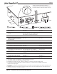
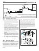
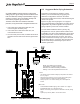
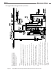
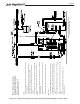
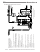
Table Of Contents
- Cover
- TABLE OF CONTENTS
- General Information
- SECTION 2 Venting and Combustion Air
- SECTION 3 Gas supply and Piping
- SECTION 4 Water Flow and Headloss Data
- SECTION 5 Boiler Piping
- SECTION 6 Condensate Drain Trap
- SECTION 7 Electrical Connections
- 7.A Installation Warnings
- 7.B Main Power Connections
- 7.C Main Power Data
- 7.D Control Panel Layout
- 7.E Field Connections
- 7.E.1 Power
- 7.E.2 Dry Contacts
- 7.E.3 Temperature Sensors
- 7.E.4 Safety Chain
- 7.E.5 Isolation Valve
- 7.E.6 Heat Demands
- 7.E.7 Analog In and Analog Out
- 7.E.8 Dry Contacts. Run & Alarm
- 7.E.9 RS 485 for Cascade (Lead Lag)
- 7.E.10 RS485 BMS
- 7.F Modbus to BACnet Memory Map (4 pages)
- 7.G WiringDiagram
- 7.H High Voltage Wiring Diagrams (5 pages)
- 7.I Ladder Diagrams (8 pages)
- SECTION 8 Control Operation
- 8.A The Home Screen
- 8.B Login to Lock / Unlock the Display Screen
- 8.C Quick Start
- 8.D Configuration
- 8.E Service Screens
- 8.E.1 Burner
- 8.E.2 Digital I/O ( Input / Output )
- 8.E.3 Analog I/O
- 8.E.4 Screen Settings Timeout
- 8.E.5 History
- 8.E.6 Restart Touchscreen & Recalibrate
- 8.E.7 Factory Reset
- 8.E.8 HMI Model OEM only
- 8.E.9 BIC Model OEM only
- 8.E.10 Both Model. OEM only.
- 8.E.11 About (the Firmware)
- 8.E.12 O2 (Trim Set Point)
- 8.E.13 LMV
- 8.F Messages and USB
- 8.G Active Demands
- SECTION 9 Parameter Tables (3 pages)
- SECTION 10 Initial startupInstructions
- SECTION 11 Maintenance
- SECTION 12 Troubleshooting
- SECTION 13 Replacement Parts
- 13.A Frame and Jacket Assembly, Part Numbers
- 13.B Control Panel Assembly, Part Numbers
- 13.C Blower and Burner Assembly,Part Numbers. ALL Sizes
- 13.D AC Distribution Box Assemblies and Part Numbers
- 13.E Burner Door Part Numbers
- 13.F Waterway Inlet Assembly, Part Numbers
- 13.G Waterway Outlet Assembly, Part Numbers
- 13.H Gas Train Part Numbers
- 13.I Exhaust Manifold Part Numbers

Page 29
NOTE: Domestic circulator MUST be sized for
both the indirect and the boiler.
Figure 10. Single Boiler, P/S Piping for Space Heating with Parallel Piping for indirect Tank
Control:
• Use outdoor reset to maintain building loop temperature. See Section
8.C.3 on page 67.
• Set System pump to AUTO, pump runs during space heating when
outdoor temperature is below warm weather shutdown.
• Place jumper on T-T for constant heating call; or interrupted if so
desired.
• System sensor required for outdoor reset operation in this application.
• Boiler, System and DHW pumps controlled by The Touchscreen
Control.
• Pump operation congurable in pump conguration menu. See Section
8.D.5 on page 83
• Use DHW sensor, terminals 39 and 40, or aquastat, terminals 53 and
54.
• Boiler pump must be OFF during DHW operation for DHW priority.
BMS control:
• For Modbus/BACnet BMS mapping, refer to Section 7.F on page 44
• Enable/disable boiler via T-T terminals (49, 50) for space heating.
• To enable/disable boiler for DHW using an aquastat, use terminals 53
and 54.
• To enable/disable boiler for DHW using a sensor, use terminals 39 and
40.
• BMS can control ring rate or setpoint via terminals 55 and 56. (analog
input).
• System, boiler and DHW pumps controlled by BMS or The
Touchscreen Control.
NOTE: This drawing is a schematic
representation of a piping style and is
not intended to be used as a working
installation drawing. Local code
requirements must be met.