
Installation / Operation Instruction Manual
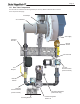
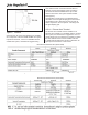
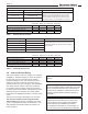
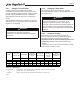
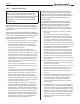
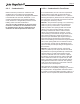
Table Of Contents
- Cover
- TABLE OF CONTENTS
- General Information
- SECTION 2 Venting and Combustion Air
- SECTION 3 Gas supply and Piping
- SECTION 4 Water Flow and Headloss Data
- SECTION 5 Boiler Piping
- SECTION 6 Condensate Drain Trap
- SECTION 7 Electrical Connections
- 7.A Installation Warnings
- 7.B Main Power Connections
- 7.C Main Power Data
- 7.D Control Panel Layout
- 7.E Field Connections
- 7.E.1 Power
- 7.E.2 Dry Contacts
- 7.E.3 Temperature Sensors
- 7.E.4 Safety Chain
- 7.E.5 Isolation Valve
- 7.E.6 Heat Demands
- 7.E.7 Analog In and Analog Out
- 7.E.8 Dry Contacts. Run & Alarm
- 7.E.9 RS 485 for Cascade (Lead Lag)
- 7.E.10 RS485 BMS
- 7.F Modbus to BACnet Memory Map (4 pages)
- 7.G WiringDiagram
- 7.H High Voltage Wiring Diagrams (5 pages)
- 7.I Ladder Diagrams (8 pages)
- SECTION 8 Control Operation
- 8.A The Home Screen
- 8.B Login to Lock / Unlock the Display Screen
- 8.C Quick Start
- 8.D Configuration
- 8.E Service Screens
- 8.E.1 Burner
- 8.E.2 Digital I/O ( Input / Output )
- 8.E.3 Analog I/O
- 8.E.4 Screen Settings Timeout
- 8.E.5 History
- 8.E.6 Restart Touchscreen & Recalibrate
- 8.E.7 Factory Reset
- 8.E.8 HMI Model OEM only
- 8.E.9 BIC Model OEM only
- 8.E.10 Both Model. OEM only.
- 8.E.11 About (the Firmware)
- 8.E.12 O2 (Trim Set Point)
- 8.E.13 LMV
- 8.F Messages and USB
- 8.G Active Demands
- SECTION 9 Parameter Tables (3 pages)
- SECTION 10 Initial startupInstructions
- SECTION 11 Maintenance
- SECTION 12 Troubleshooting
- SECTION 13 Replacement Parts
- 13.A Frame and Jacket Assembly, Part Numbers
- 13.B Control Panel Assembly, Part Numbers
- 13.C Blower and Burner Assembly,Part Numbers. ALL Sizes
- 13.D AC Distribution Box Assemblies and Part Numbers
- 13.E Burner Door Part Numbers
- 13.F Waterway Inlet Assembly, Part Numbers
- 13.G Waterway Outlet Assembly, Part Numbers
- 13.H Gas Train Part Numbers
- 13.I Exhaust Manifold Part Numbers

Page 15
a tee with the branch connection sized to allow for
insertion of a ue gas analyzer probe. The branch
connection must be resealable with a cap or other
means to ensure the vent system remains sealed.
(See Figure 4)
Consideration must be given to the placement and
orientation of the ue gas sampling port to ensure that
condensate is free to ow back into the unit and not
collect anywhere in the vent system - including in the
ue gas sampling port.
2.B.1.b Exhaust Vent Terminal -
An exhaust vent terminal must be installed. If an
exhaust vent terminal is not available with the certied
vent system, the manufacturer suggests the use of a
coupler tting from the certied vent system into which
the vent terminal screen can be installed. Be sure
to install and terminate both vent and combustion air
pipes per the instructions in this section.
Figure 4. Test Port
Table 4. Allowable Single Wall Stainless Steel Vent Suppliers and Part Numbers
Manufacturer Model Numbers (abbreviated)
external to the unit. A ue gas sampling port available
as a component of the ULC S636 certied vent system
is preferred. However, if one is not available with the
certied vent system, manufacturer suggests using
Table 5. Allowable Polypropylene Vent Manufacturers / Trade Names
Manufacturer Model Numbers (abbreviated)