
Installation / Operation Instruction Manual
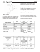
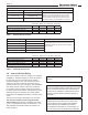
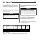
Table Of Contents
- Cover
- TABLE OF CONTENTS
- General Information
- SECTION 2 Venting and Combustion Air
- SECTION 3 Gas supply and Piping
- SECTION 4 Water Flow and Headloss Data
- SECTION 5 Boiler Piping
- SECTION 6 Condensate Drain Trap
- SECTION 7 Electrical Connections
- 7.A Installation Warnings
- 7.B Main Power Connections
- 7.C Main Power Data
- 7.D Control Panel Layout
- 7.E Field Connections
- 7.E.1 Power
- 7.E.2 Dry Contacts
- 7.E.3 Temperature Sensors
- 7.E.4 Safety Chain
- 7.E.5 Isolation Valve
- 7.E.6 Heat Demands
- 7.E.7 Analog In and Analog Out
- 7.E.8 Dry Contacts. Run & Alarm
- 7.E.9 RS 485 for Cascade (Lead Lag)
- 7.E.10 RS485 BMS
- 7.F Modbus to BACnet Memory Map (4 pages)
- 7.G WiringDiagram
- 7.H High Voltage Wiring Diagrams (5 pages)
- 7.I Ladder Diagrams (8 pages)
- SECTION 8 Control Operation
- 8.A The Home Screen
- 8.B Login to Lock / Unlock the Display Screen
- 8.C Quick Start
- 8.D Configuration
- 8.E Service Screens
- 8.E.1 Burner
- 8.E.2 Digital I/O ( Input / Output )
- 8.E.3 Analog I/O
- 8.E.4 Screen Settings Timeout
- 8.E.5 History
- 8.E.6 Restart Touchscreen & Recalibrate
- 8.E.7 Factory Reset
- 8.E.8 HMI Model OEM only
- 8.E.9 BIC Model OEM only
- 8.E.10 Both Model. OEM only.
- 8.E.11 About (the Firmware)
- 8.E.12 O2 (Trim Set Point)
- 8.E.13 LMV
- 8.F Messages and USB
- 8.G Active Demands
- SECTION 9 Parameter Tables (3 pages)
- SECTION 10 Initial startupInstructions
- SECTION 11 Maintenance
- SECTION 12 Troubleshooting
- SECTION 13 Replacement Parts
- 13.A Frame and Jacket Assembly, Part Numbers
- 13.B Control Panel Assembly, Part Numbers
- 13.C Blower and Burner Assembly,Part Numbers. ALL Sizes
- 13.D AC Distribution Box Assemblies and Part Numbers
- 13.E Burner Door Part Numbers
- 13.F Waterway Inlet Assembly, Part Numbers
- 13.G Waterway Outlet Assembly, Part Numbers
- 13.H Gas Train Part Numbers
- 13.I Exhaust Manifold Part Numbers

Page 14
SECTION 2 Venting and Combustion Air
2.A General Venting Information
WARNING
Selection of improper vent materials for installations
that are installed in closets, or will be operated in high
ambient temperature levels, may lead to property
damage, personal injury, or death.
WARNING
Failure to use the appropriate vent material,
installation techniques, or glues and sealants could
lead to vent failure causing property damage, personal
injury or death.
WARNING
Use of cellular core PVC (ASTM F891), cellular core
CPVC, or Radel® (polyphenolsulfone) in non-metallic
venting systems is prohibited and that covering non-
metallic vent pipe and ttings with thermal insulation is
prohibited.
WARNING
All venting must be installed according to this manual
and any other applicable local codes, including but
not limited to, ANSI Z223.1/NFPA 54, CSA B149.1,
CSAB149.2 and ULC S636. Failure to follow this
manual and applicable codes may lead to property
damage, severe injury, or death.
If the system temperatures are unknown at the time
of installation, class IIC or higher venting material is
recommended.
This unit is certied to vent as a Category II (negative
pressure condensing) or Category IV (positive pressure
condensing) appliance. It may be installed with vent
materials meeting the standards listed in Table 6.
The vent can terminate through the roof, or through an
outside wall.
All installations must be done following the vent
supplier’s recommended installation techniques. If
these are not available, refer to the Manufacturer
recommendations for the material used.
2.B Vent and Air Pipe Material
This unit requires a special venting system. Refer to
venting supplier’s instructions for complete parts list and
method of installation. The manufacturers and product
lines listed in Table 4 and Table 5 have been tested
and authorized to safely operate with this equipment.
Suppliers of stainless steel and polypropylene venting
that are not listed on these tables are not permitted for
use with this appliance.
Do not mix venting suppliers and models in venting
systems. Failure to comply could result in personal
injury, property damage, or death.
Installations must comply with applicable national, state
and local codes.
2.B.1 Venting Requirements Unique to
Canada
These high eciency boilers are Vent Category II and
IV units. Per the requirements of CAN/CSA-B149.1,
only BH vent systems can be connected to these units
and such vent systems, either ULC S636 certied
stainless steel or other ULC S636 certied BH vent (eg.
plastics) must be installed per the vent manufacturer’s
certied installation instructions.
It is the responsibility of the appropriately licensed
technician installing this unit to use ULC S636 certied
vent material consistent with the requirements as
described in the Venting and Combustion Air section.
Class I venting systems are suitable for gas-red units
producing ue gas temperature of more than 135°C
(275°F), but not more than 245°C (473°F).
Class II venting systems are suitable for gas-red units
producing ue gas temperatures of 135°C or less.
Class II venting systems are further classied into four
temperature ratings as follows:
A Up to and including 65°C / 149°F
B Up to and including 90°C / 194°F
C Up to and including 110°C / 230°F and
D Up to and including 135°C / 275°F
2.B.1.a Flue Gas Sampling Port -
It is also the responsibility of the installer to ensure that
a ue gas sampling port is installed in the vent system.
This ue gas sampling port must be installed near
the ue connection of the unit: within 2 feet of the ue
connection. There is no ue gas sampling port internal
to the unit, so one must be installed in the vent system