
Installation / Operation Instruction Manual
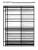
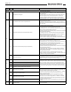
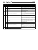
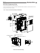
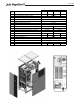

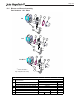
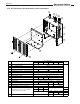
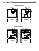
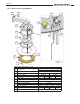
Table Of Contents
- Cover
- TABLE OF CONTENTS
- General Information
- SECTION 2 Venting and Combustion Air
- SECTION 3 Gas supply and Piping
- SECTION 4 Water Flow and Headloss Data
- SECTION 5 Boiler Piping
- SECTION 6 Condensate Drain Trap
- SECTION 7 Electrical Connections
- 7.A Installation Warnings
- 7.B Main Power Connections
- 7.C Main Power Data
- 7.D Control Panel Layout
- 7.E Field Connections
- 7.E.1 Power
- 7.E.2 Dry Contacts
- 7.E.3 Temperature Sensors
- 7.E.4 Safety Chain
- 7.E.5 Isolation Valve
- 7.E.6 Heat Demands
- 7.E.7 Analog In and Analog Out
- 7.E.8 Dry Contacts. Run & Alarm
- 7.E.9 RS 485 for Cascade (Lead Lag)
- 7.E.10 RS485 BMS
- 7.F Modbus to BACnet Memory Map (4 pages)
- 7.G WiringDiagram
- 7.H High Voltage Wiring Diagrams (5 pages)
- 7.I Ladder Diagrams (8 pages)
- SECTION 8 Control Operation
- 8.A The Home Screen
- 8.B Login to Lock / Unlock the Display Screen
- 8.C Quick Start
- 8.D Configuration
- 8.E Service Screens
- 8.E.1 Burner
- 8.E.2 Digital I/O ( Input / Output )
- 8.E.3 Analog I/O
- 8.E.4 Screen Settings Timeout
- 8.E.5 History
- 8.E.6 Restart Touchscreen & Recalibrate
- 8.E.7 Factory Reset
- 8.E.8 HMI Model OEM only
- 8.E.9 BIC Model OEM only
- 8.E.10 Both Model. OEM only.
- 8.E.11 About (the Firmware)
- 8.E.12 O2 (Trim Set Point)
- 8.E.13 LMV
- 8.F Messages and USB
- 8.G Active Demands
- SECTION 9 Parameter Tables (3 pages)
- SECTION 10 Initial startupInstructions
- SECTION 11 Maintenance
- SECTION 12 Troubleshooting
- SECTION 13 Replacement Parts
- 13.A Frame and Jacket Assembly, Part Numbers
- 13.B Control Panel Assembly, Part Numbers
- 13.C Blower and Burner Assembly,Part Numbers. ALL Sizes
- 13.D AC Distribution Box Assemblies and Part Numbers
- 13.E Burner Door Part Numbers
- 13.F Waterway Inlet Assembly, Part Numbers
- 13.G Waterway Outlet Assembly, Part Numbers
- 13.H Gas Train Part Numbers
- 13.I Exhaust Manifold Part Numbers

Page 123
Error
Code
Diag.
Code
Meaning for the LMV3 Corrective Action
Note: Diagnostic codes are additive. If a diagnostic code appears that is not on this list, it is a combination of multiple diagnostic codes.
0 Position error
Verify that the valve connected to the fuel actuator is not bound. Ensure
that the torque requirements of the valve are less than the output of the
fuel actuator. If everything checks out okay, replace the SQM33 actuator.
1 Line interruption
Check the wiring between the fuel actuator and LMV3 terminal X54.
There should more > 0.5 VDC across pins 2 and 5 and across pins 2 and 6.
If no fuel actuator exists, choose a fuel train option (parameter 201/301)
that does not require a fuel actuator.
8 Curve too steep in terms of ramp rate See error code 84.
86 16 Step deviation in comparison with last referencing
The fuel actuator is bound.
1) Check the setting of parameter 613:00 (fuel 0) and 614 (fuel 1) to
ensure the actuator type is set correctly.
2) Check to see if the actuator gets bound somewhere along its working
range. This can be done changing the home position of the actuator in
standby (no alarm).
3) Ensure that the torque of the actuator is sufficient for the application.
Any # Error air actuator
An error occurred pertaining to the air actuator. See diagnostic codes for
more information.
0 Position error
Verify that the valve / damper connected to the air actuator is not bound.
Ensure that the torque requirements of the valve / damper are less than
the output of the air actuator. If everything checks out okay, replace the
SQM33 actuator.
1 Line interruption
Check the wiring between the air actuator and LMV3 terminal X53. There
should more > 0.5 VDC across pins 2 and 5 and across pins 2 and 6. If no
air actuator exists, choose a fuel train option (parameter 201/301) that
does not require an air actuator.
8 Curve too steep in terms of ramp rate See error code 84.
16 Step deviation in comparison with last referencing
The air actuator is bound.
1) Check the setting of parameter 613:01 to ensure the actuator type is
set correctly.
2) Check to see if the actuator gets bound somewhere along its working
range. This can be done changing the home position of the actuator in
standby (no alarm).
3) Ensure that the torque of the actuator is sufficient for the application.
Any # Error flame signal acquisition
3 Short-circuit of sensor
86
Check the wiring of the QRB… flame detector and reset the fault. If the
fault occurs continuously, replace the QRB… flame detector.
87
93