
Installation / Operation Instruction Manual
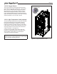

Table Of Contents
- Cover
- TABLE OF CONTENTS
- General Information
- SECTION 2 Venting and Combustion Air
- SECTION 3 Gas supply and Piping
- SECTION 4 Water Flow and Headloss Data
- SECTION 5 Boiler Piping
- SECTION 6 Condensate Drain Trap
- SECTION 7 Electrical Connections
- 7.A Installation Warnings
- 7.B Main Power Connections
- 7.C Main Power Data
- 7.D Control Panel Layout
- 7.E Field Connections
- 7.E.1 Power
- 7.E.2 Dry Contacts
- 7.E.3 Temperature Sensors
- 7.E.4 Safety Chain
- 7.E.5 Isolation Valve
- 7.E.6 Heat Demands
- 7.E.7 Analog In and Analog Out
- 7.E.8 Dry Contacts. Run & Alarm
- 7.E.9 RS 485 for Cascade (Lead Lag)
- 7.E.10 RS485 BMS
- 7.F Modbus to BACnet Memory Map (4 pages)
- 7.G WiringDiagram
- 7.H High Voltage Wiring Diagrams (5 pages)
- 7.I Ladder Diagrams (8 pages)
- SECTION 8 Control Operation
- 8.A The Home Screen
- 8.B Login to Lock / Unlock the Display Screen
- 8.C Quick Start
- 8.D Configuration
- 8.E Service Screens
- 8.E.1 Burner
- 8.E.2 Digital I/O ( Input / Output )
- 8.E.3 Analog I/O
- 8.E.4 Screen Settings Timeout
- 8.E.5 History
- 8.E.6 Restart Touchscreen & Recalibrate
- 8.E.7 Factory Reset
- 8.E.8 HMI Model OEM only
- 8.E.9 BIC Model OEM only
- 8.E.10 Both Model. OEM only.
- 8.E.11 About (the Firmware)
- 8.E.12 O2 (Trim Set Point)
- 8.E.13 LMV
- 8.F Messages and USB
- 8.G Active Demands
- SECTION 9 Parameter Tables (3 pages)
- SECTION 10 Initial startupInstructions
- SECTION 11 Maintenance
- SECTION 12 Troubleshooting
- SECTION 13 Replacement Parts
- 13.A Frame and Jacket Assembly, Part Numbers
- 13.B Control Panel Assembly, Part Numbers
- 13.C Blower and Burner Assembly,Part Numbers. ALL Sizes
- 13.D AC Distribution Box Assemblies and Part Numbers
- 13.E Burner Door Part Numbers
- 13.F Waterway Inlet Assembly, Part Numbers
- 13.G Waterway Outlet Assembly, Part Numbers
- 13.H Gas Train Part Numbers
- 13.I Exhaust Manifold Part Numbers

Page 116
11.B.7 Heat Exchanger Tubes
Black carbon soot build-up on the internal surfaces
of the heat exchanger is caused by one or more of
the following: incomplete combustion, combustion air
problems, venting problems or boiler short-cycling. Soot
buildup or other debris on the heat exchanger may
restrict the ue passages.
If black carbon soot buildup on the heat exchanger is
suspected, disconnect the electrical supply to the unit
and turn o the gas supply by closing the manual gas
valve on the unit. Access the heat exchanger through
the heat exchanger shrouds. Removal of the outer
baes may be required for proper inspection. Use a
ashlight. If there is a buildup of black carbon soot
or other debris on the heat exchanger, clean per the
following:
CAUTION
Black carbon soot buildup on a dirty heat
exchanger can be ignited by a random spark or
ame. To prevent this from happening, dampen the
soot deposits with a wet brush or ne water spray
before servicing the heat exchanger.
1. Shut o the main power supply to the boiler.
2. Turn o all manual gas valves connecting the boiler
to the main gas supply line.
3. Remove the blower assembly and burner from the
heat exchanger.
4. Disconnect the condensate drain line.
5. Attach a longer hose to the drain and run it to a
bucket.
6. Clean the heat exchanger by brushing away any
light accumulations of soot and debris. Use a non
metallic brush with soft bristles to avoid damaging
the surfaces of the heat exchanger tubes.
7. Once the tubes have been brushed clean, rinse the
tubes and combustion chamber with a small amount
of water to rinse all of the debris out of the bottom
of the ue collector and into the longer condensate
trap line which is being diverted into a separate
container.
WARNING
Failure to rinse the debris from the heat exchanger
and temporary drain line may lead to clogged
condensate lines, traps and neutralizers.
Condensate pumps (if used) may also be damaged
from the debris left behind, possibly causing
property damage.
8. To place the unit back in operation, install all
removed components in the reverse order. Be sure
all gaskets are in place as the components are
installed. Replace any damaged gaskets. Do not
reuse damaged gaskets.
9. Place the unit into operation, checking all gas
connections for leaks. Conrm all fasteners are tight.
11.B.8 Gas Pressure Switches
The high and low pressure gas switches are 24 VDC
manual reset switches that act to cut power to the
interlock circuit if the gas pressure is too low or too high
for proper operation. There is a manual reset on both.
The gas pressure switches used are integrally vent
limited and do not require venting to atmosphere. To
remove a switch, remove the screw on the plastic
housing and pull the clear cover o. Disconnect the
three (3) wires from the screw terminals. Twist the
switch o the pipe nipple. Reassemble in reverse order.
Set the low pressure gas switch to 3” w.c.
Set the high pressure gas switch to 15”w.c.”
11.B.9 Pressure Transmitters
The pressure transmitters are powered with 5 VDC
from the controller and output a 0.5 to 4.5 VDC signal
from 0 to 4 inches water column dierential pressure. If
the pressure transmitters do not read the same value
within a prescribed margin of error a lockout will occur
and an “Air Pressure Drift Error” will be displayed. If
this occurs, check the transmitter electrical connections
and that the pressure sense tubing is intact and there
are no kinks. If the condition is not resolved, replace the
transmitters.
The transmitter values are displayed on the Analog I/O
Output menu; toggle to the right to display Pressure
1 and Pressure 2 and compare the values during fan
operation.