
Installation / Operation Instruction Manual
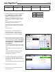
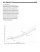
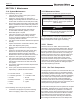
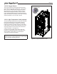
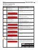

Table Of Contents
- Cover
- TABLE OF CONTENTS
- General Information
- SECTION 2 Venting and Combustion Air
- SECTION 3 Gas supply and Piping
- SECTION 4 Water Flow and Headloss Data
- SECTION 5 Boiler Piping
- SECTION 6 Condensate Drain Trap
- SECTION 7 Electrical Connections
- 7.A Installation Warnings
- 7.B Main Power Connections
- 7.C Main Power Data
- 7.D Control Panel Layout
- 7.E Field Connections
- 7.E.1 Power
- 7.E.2 Dry Contacts
- 7.E.3 Temperature Sensors
- 7.E.4 Safety Chain
- 7.E.5 Isolation Valve
- 7.E.6 Heat Demands
- 7.E.7 Analog In and Analog Out
- 7.E.8 Dry Contacts. Run & Alarm
- 7.E.9 RS 485 for Cascade (Lead Lag)
- 7.E.10 RS485 BMS
- 7.F Modbus to BACnet Memory Map (4 pages)
- 7.G WiringDiagram
- 7.H High Voltage Wiring Diagrams (5 pages)
- 7.I Ladder Diagrams (8 pages)
- SECTION 8 Control Operation
- 8.A The Home Screen
- 8.B Login to Lock / Unlock the Display Screen
- 8.C Quick Start
- 8.D Configuration
- 8.E Service Screens
- 8.E.1 Burner
- 8.E.2 Digital I/O ( Input / Output )
- 8.E.3 Analog I/O
- 8.E.4 Screen Settings Timeout
- 8.E.5 History
- 8.E.6 Restart Touchscreen & Recalibrate
- 8.E.7 Factory Reset
- 8.E.8 HMI Model OEM only
- 8.E.9 BIC Model OEM only
- 8.E.10 Both Model. OEM only.
- 8.E.11 About (the Firmware)
- 8.E.12 O2 (Trim Set Point)
- 8.E.13 LMV
- 8.F Messages and USB
- 8.G Active Demands
- SECTION 9 Parameter Tables (3 pages)
- SECTION 10 Initial startupInstructions
- SECTION 11 Maintenance
- SECTION 12 Troubleshooting
- SECTION 13 Replacement Parts
- 13.A Frame and Jacket Assembly, Part Numbers
- 13.B Control Panel Assembly, Part Numbers
- 13.C Blower and Burner Assembly,Part Numbers. ALL Sizes
- 13.D AC Distribution Box Assemblies and Part Numbers
- 13.E Burner Door Part Numbers
- 13.F Waterway Inlet Assembly, Part Numbers
- 13.G Waterway Outlet Assembly, Part Numbers
- 13.H Gas Train Part Numbers
- 13.I Exhaust Manifold Part Numbers

Page 112
Table 24. BIC Status and LMV Status
10.C Shutting Down the Unit
This step must be performed by a qualied service
person.
1. Turn o the main electrical disconnect switch.
2. Close all manual gas valves.
3. If freezing is anticipated, drain the unit and be sure
to also protect the building piping from freezing. All
water must be removed from the heat exchanger or
damage from freezing may occur.
10.D Restarting the Unit
If the system has been drained, see 10.A for instructions
on proper lling and purging.
1. Turn o the main electrical disconnect switch.
2. Close all manual gas valves.
3. Wait ve minutes.
4. Set the aquastat or thermostat to its lowest setting.
5. Open all manual gas valves.
6. Reset all safety switches (pressure switch, manual
reset high limit, etc.).
7. Set the temperature controller to the desired
temperature setting and switch on the electrical
power.
8. The unit will go through a prepurge period and
ignitor warm-up period, followed by ignition.
BIC Status LMV States
Phase Phase
Standy 12 Standby
Call For Heat
LMV Enable
22 Blower On
24 Component Calibration
Pressure Xmitter
Verification
30 Prepurge
36 Move to Ignition Position
Read (via Modbus) at
38 Igniter On
ACC State and Display 40 Main Fuel On
Touchscreen 42 Ignitor Off/Verify Main Burn
60 Run
Fan Speed Governed by
SIT Demand Signal
End Call for Heat
LMV Disable
70 Post Purge
74 Shutdown
Standby Standby
10.E Controllers
This unit utilizes three (3) separate controllers to
manage system functions, burner management and air/
fuel ratio control:
- Burner Integrated Control (BIC)
- Linkageless Modulating Valve (LMV)
- Oxygen Controller (O2C)
These controllers communicate with each other
via voltage and current signals, and serial digital
communication using Modbus protocol. The BIC also
communicates with the touch screen display and all
user inputs.
When there is a call for heat the BIC will provide an
enable signal to the LMV which tells the LMV to initiate
burner operation. For this signal to be sent and acted
upon, the safety circuit must be satised and both
controllers must be in standby mode.
The system pressure sensors, which measure the
overall system pressure drop must also read zero in
order for the Safety Status to be veried.
The Safety Circuit status can be veried on the
Services/Digital I/O screen. Once the LMV is enabled it
will proceed through the startup states listed in Table 24
until it gets to Run. Once in Run, the LMV will receive
a ring rate demand from the BIC and position the fuel
and air dampers and blower speed accordingly.
After the burner has been on for two (2) minutes
the oxygen trim loop will be enabled and the blower
speed will be adjusted to maintain the preset oxygen
concentration in the boiler exhaust.
The MagnaTech FT is a direct ignition system and does
not use a separate pilot. A spark ignition is used to
light the main burner at ta pre-set reduced ring rate. If
the main ame is not detected during the “verify main
burner” stage, the LMV will enter a ‘Lock-out’ mode and
a ‘Flame Out’ error will appear on the display screen.
If the maximum attempts for ignition has not been
reached, the system will perform an automatic reset and
the ignition sequence will be repeated.
NOTE: Three attempts for ignition is standard before
a ‘Hard’ lock-out occurs. If a hard lock-out occurs, the
system must be manually reset using the reset button
on the display unit. CSD-1 units have a single attempt
for ignition prior to a hard lock-out.
If the call for heat is satised normally, the BIC will
remove the enable signal and the LMV will de-energize
the fuel valves and enter postpurge. Any time there
is an interruption of the BIC safety circuit, both the
LMV enable signal and LMV safety loop signal will be
removed, triggering a burner shutdown. Along with
the circuit components identied in the System Ladder
Logic, the system dierential pressure is continuously
monitored while the burner is in operation.