
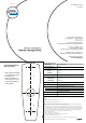
User's Manual


Introduction
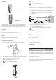
Smart Mullion Reader
Optional Back Box
The reader outputs a PAC format suitable for PAC 202/512 access controllers. They are used in security
applications and can be installed in new installations or as an upgraded reader in existing proximity access
control systems. Each reader incorporates a LED which is controlled by the security system and provides
feedback to a person wishing to enter.
External Use
Mount the reader on a suitable external single gang surface mount box.
Make sure that the wire bundle to the reader has an IP rating of at least IP67.
Use warming pads if the temperature of the reader is expected to fall below -10ºC (14ºF).
Handling
Handle the reader with care. Do not damage/drop unit before installation.
Smart Mullion Reader Installation
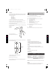
1. Remove the cover by holding the unit as shown and pulling the cover from the top as illustrated.
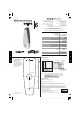
2. If necessary, drill holes for the mounting screws in the wall or mounting box on which the reader unit will
be placed. Use the template provided. Alternately a back box can be used.
3. Place the controller and power supply cable through the grommit hole.
4. Drill the holes in the wall as indicated by the arrows.
Make sure that you don't drill through the cable.
Wiring
1. Read the instructions before wiring.
2. The request to exit and door contact can be wired for 4-state if required.
Note
Using two readers, for in and out, on one door channel will require one reader to be powered separately.
See Technical Bulletin TB151 "How to Connect High-Current Readers to PAC Access Controllers"
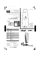
1. Connect the wiring as indicated in the diagram to the socket. Check your circuit diagram for the colour
coding of the circuit wiring.
Connect the 0V reference and 0V (if provided in the power supply) to the ground (GND) Wire.
Connect the signal and optional wires.
Connect the LED wire.
Connect the +12Vdc wire last.
2. Place the reader on the wall. Make sure the wires are not crushed.
3. Insert and hand tighten the screws.
4. Check that the reader is level before tightening the screws.
Excessive tightening of screws may deform the casing, resulting in a damaged unit.
THIS WILL VOID THE WARRANTY.
5. Replace the cover.
6. Power up the reader.
Note
The unit needs approximately 13 seconds to set up
before it can respond to a valid smart card.
Maintenance
Once installed the reader requires no maintenance
Troubleshooting
If the reader doesn't respond when a valid smart card is presented, check the following:
If the problem still exists, uninstall the reader and send it back to the PAC. If the reader is within the warranty
period then another will be sent free of charge.
Warranty
Each reader comes with a 3-year warranty from the date of dispatch. The warranty is void if the instructions
contained within this document have not been adhered to.
Symptom
LED is not lit
LED is orange/indeterminate
or buzzer sounds low
Reader doesn't respond
Possible Cause
No power to the reader
Voltage to the reader is below
minimum required level
Invalid card or card is faulty or
Wiring to the controller is faulty.
Check
Check the power supply to the reader.
Check the power supply to the reader
Check reader with another valid smart
card; if problem persists check wiring
White
62
45