
User`s guide


6
Getting Started
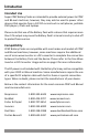
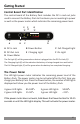
Control Board Part Identification
The control board of the Battery Pack includes the DC in and out jacks
used to connect the Battery Pack to the device you are wanting to power
as well as the power meter which indicates the remaining power level.
A DC In Jack B Power Button C Full Charged Light
D DC Out Jack E Charging Light F On Light
G Power Meter
EF
CBAD
G
The On Light (F) will be green when a device is plugged into the DC Out Jack (D).
The Charging Light (E) will be red when the battery is being charged via a wall outlet.
The Full Charged Light (C) will be green when the battery has completed charging.
The Power Meter
The LED light power meter indicates the remaining power level of the
Battery Pack. The power meter may be activated after the first time you
charge your Battery Pack. Press the Power button, the number of LED lights
displayed will show you the power level of the Battery Pack.
4 green LED lights 85-100% 3 green LED lights 50-85%
2 green LED lights 15-50% 1 green LED light < 15%
If the power meter does not work, hold down the Power button for 10-15
seconds or until the LED lights display. This will activate the power meter.