
Instruction manual


71
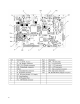
Load Cell
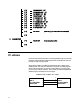
The Load Cell can be tested for proper analog voltage input and millivolt output
by measuring the voltage on the Main Logic PCB. To check the input voltage
across +EXC & -EXC, place your meter on volts and put the positive lead on the
left pin of F1 and the negative lead on the left pin of F4. You should be reading a
steady +10VDC +/- 0.25VDC.
If the Excitation voltage is good, the signal output can be checked across +SIG &
-SIG. Set the meter to read in millivolts (mV). Put the positive lead on the left pin
of F2 and negative lead on the left pin of F3. With no weight on the platter, you
should read zero data. As you add weight to the platter, the voltage should rise
and be linear if equal weight is added each time. If the output is linear and
correct, but no weight is displayed, replace the Main Logic PCB. If there is no
output from the load cell, but correct input voltage, replace the load cell.
Warning Message
INPUT TOO BIG
The input is too big.
INPUT TOO SMALL
The input is too small.
TOO MUCH INPUT
The input is out of limit.
WRONG CODENR.
The code number is invalid.
KEY NO FUNCTION
The key has no function.
KEY BLOCKED
The key is disabled. Check the KEYBOARD CONFIGURE.
PLU NOT FOUND
The entered PLU number does not exist.
AG NOT FOUND