
Instruction manual


69
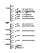
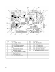
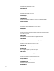
Main Logic PCB
The Main Logic PCB receives +24VDC from the Power Supply and uses this to
supply +10VDC and +5VDC to other components. The Main Logic PCB controls
all functions in the unit including the thermal printer. Inputs and Outputs to the
Main Logic include the Label Taken Sensor, Gap Sensor, Printhead, Stepper
Motor, Rewind Motor, Load Cell and etc. The following Figure shows the
locations of the various components and connectors on the Main Logic PCB.
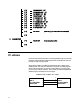
If the volages are not within the range specified, and the Power Supply voltage is
correct, replace the Main Logic PCB.
NOTE: WHEN REPLACING THE MAIN LOGIC PCB, THE UNIT MUST BE
REFLASHED.