
Instruction manual


68
working fuse
backup fuse
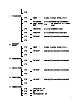
Flow control: None
POWER SUPPLY
Following is a list of symptoms that could occur, and the recommended action to
correct the problem.
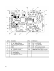
Place the Power Switch to the OFF position. Remove the platter, spider, and top cove.
To check the +24VDC output voltage from the Power Supply terminal between the
terminals marked +V and GND, the acceptable output range is +24VDC +/-0.50 VDC.
If the voltage is normal, the Power Supply should be good, and the problem should be
suspected as being in the Main Logic PCB or a component that connects to the Main
Logic PCB.
If the output voltage is zero, check the 120 VAC input voltage. If the correct AC input
voltage is present, but there is no +24 VDC output, replace the Power Supply.
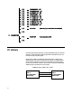
If no voltage is present, check the fuse (240VAC 4A) on the power supply. If the fuse
is OK, check AC input at the Line Cord Jack between the Red wire and Black wire. If
the 120VAC is present, suspect a defective power switch. If 120 VAC is not present at
the jack, check the fuse (240VAC 3A) installed in the Line Cord Jack, as shown in the
following Figure. If the fuse is OK, verify voltage is present at the AC wall outlet.