VTR1004 DIGITAL VIDEO RECORDER USER GUIDE VER 2.2.3 1st Edition Thank you for purchasing this Digital Video Recorder. Before using the Digital Video Recorder, please ensure that you read and understand this USER GUIDE. Please store the USER GUIDE in an easily accessible location. Before connecting and installing any third party cameras, monitors, alarms and computers, please refer to the appropriate instruction manual for proper operation.
SAFETY PRECAUTIONS CAUTION RISK OF ELECTRIC SHOCK DO NOT OPEN CAUTION: TO REDUCE THE RISK OF ELECTRIC SHOCK, DO NOT REMOVE COVER (OR BACK). NO USER-SERVICEABLE PARTS INSIDE. REFER SERVICING TO QUALIFIED SERVICE PERSONNEL. The lightning flash with arrowhead symbol, within an equilateral triangle, is intended to alert the user to the presence of uninsulated “dangerous voltage” within the product’s enclosure that may be of sufficient magnitude to constitute a risk of electric shock to persons.
TABLE OF CONTENTS ■ PRODUCT CONTENTS ■ INTRODUCTION 1. FRONT PANEL 2. REAR PANEL ■ POWER ON/OFF 1. TURNING ON THE POWER 2. TURNING OFF THE POWER ■ MAIN MENU 1. MENU SYSTEM 8 9 11 11 12 1.1. SELECTING THE MENU 12 1.2. POSITIONING THE YELLOW COLOR HIGHLIGHT 12 1.3. SETTING AN OPTION 12 1.4. SPECIAL BUTTON FUNCTION 2. ENTERING AND EXIT FROM MAIN MENU 2.1. ENTERING THE MAIN MENU 2.2. EXIT FROM THE MAIN MENU 3. MAIN MENU 3.1. DEVICE 3.1.1. CAMERA 3.1.2. ALARM 12 13 13 13 14 14 14 15 3.2. RECORD 16 3.
3.5. LOG LIST 27 3.6. INFORMATION 27 3.7 SHUTDOWN 27 ■ SYSTEM OPERATION 1. LIVE MODE 28 1.1. STATUS BAR ON/OFF 29 1.2. CONFIGURATION UPLOAD/DOWNLOAD 29 1.3. LOG LIST DOWNLOAD 29 1.4. EVENT DATA BACKUP WITHOUT MONITOR 29 2. RECORD MODE 30 2.1. MANUAL RECORD MODE 30 2.2. EVENT RECORD MODE 31 2.3. SCHEDULE RECORD MODE 32 3. SEARCH & PLAYBACK MODE 33 3.1. SEARCH MODE 33 3.2. PLAYBACK MODE 35 4. INSTANT BACKUP 35 ■ PC CLIENT SOFTWARE 1. INSTALLING PROCEDURES 38 2.
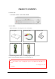
PRODUCT CONTENTS ● SYSTEM UNIT 4 CHANNEL DIGITAL VIDEO RECORDER ● ACCESSORIES Make sure that the following accessories are included. ① User guide ② Camera Cable ④ Signal Ground Cable ⑤ USB Cable ③ Software CD In case that the product is defective or damaged, please contact your dealer. Please keep the packaging materials for transport purposes. WARNING • Don’t turn off the power or unplug the power cord while hard disk drive is in operation.
INTRODUCTION This Digital Video Recorder is powerful and cost-effective. User Friendly Interface Easy on-screen system setup and operation. Detailed on-screen display record status, storage usage, date, time, power loss, video loss, alarm status and camera title. High Performance Highly stable embedded Linux operating system. Highly stable database management Superior picture quality : more than 450 TV line recording Instant backup to CF card Fast backup through USB 2.
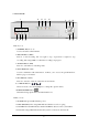
1. FRONT PANEL 11 1 2 3 4 12 13 14 8 5 6 10 7 9 ● Buttons (1~9) 1. NUMERIC Buttons (1~4) Used to select the camera number 2. RECORD Button (REC) Press it to start recording, and once again to stop. A password is required to stop recording. The orange LED is on when the recording is in progress. 3. SEARCH Button (SER) Press it to search the recorded image data. 4. FUNCTION Button (Fn) Used in combination with other buttons, it allows you to access the special functions.
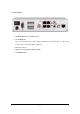
- 2. REAR PANEL 1. POWER: Main Power ON/OFF switch 2. DC POWER IN This 12 mm circular type jack accepts the DVR power module plug or other right positive source of 10~30V DC at 3 amperes. 3. RS-232 Connector 4. Signal Ground Terminal (SIGNAL GND) 5.
(Remark) Video Input Connector Specification 1 CHANNEL 1: VIDEO GND 2: VCC GND 3: VIDEO SIGNAL 4,5: VCC 6: AUDIO SIGNAL 7,8: AUDIO GND 2,3,4 CHANNEL 1: VIDEO GND 2: VCC GND 3: VIDEO SIGNAL 4,5: VCC 6,7,8: NC 10
POWER ON/OFF 1. TURNING ON THE POWER ① Make sure that peripherals are properly connected. ② Switch「ON」on the rear panel. The front POWER LED will light up in green. Please wait approximately 50 seconds until it start up. NOTE If the covert is set to「ON」in the camera settings, no camera image is displayed. < LIVE DISPLAY SCREEN > 2. TURNING OFF THE POWER ① In the LIVE mode, press the MENU/ENTER button, and then it goes to MAIN MENU.
MAIN MENU 1. MENU SYSTEM The on-screen menus allow you to set up all the features. All setup data is safe from power loss and stored in the hard disk. 1.1. SELECTING THE MENU Press the MENU/ENTER ( ) Button to select a menu item. If you press the ESC button, it returns to the previous menu. 1.2. POSITIONING THE YELLOW COLOR HIGHLIGHT Use up and down buttons to position the menu highlight. Press left and right buttons to move to the next value in the selected menu. 1.3.
2. ENTERING AND EXIT FROM MAIN MENU 2.1. ENTERING THE MAIN MENU < PASSWORD POP-UP WINDOW FOR ENTERING THE MAIN MENU > ① Press MENU/ENTER button. Password pop-up window is displayed. ② Press MENU/ENTER button after entering administrator’s password. Then the MAIN MENU screen is displayed. NOTE There is no default password at factory default. Press MENU/ENTER button again when password pop-up window is displayed. < MAIN MENU SCREEN > 2.2.
3. MAIN MENU 3.1. DEVICE CAMERA and ALARM can be configured in this menu. < DEVICE MENU SCREEN > 3.1.1. CAMERA < CAMERA MENU SCREEN > Firstly, press the NUMERIC Button (1~4) to select a desired camera. ① TITLE: The camera title can be up to 9 characters. - Press MENU/ENTER button and press the UP/DOWN button to select the character. ② BRIGHTNESS / CONTRAST: Adjusts brightness and contrast. - When positioned to BRIGHTNESS / CONTRAST, press MENU/ENTER button, pop-up window is displayed.
③ PTZ: This is used to select the protocol of connected PTZ cameras. ④ COVERT: Hidden camera function. If the COVERT is ON, then the camera will not be shown in the live display mode or playback mode while it’s recording. ⑤ SEQUENCE: OFF or select camera switch interval from 1sec to 10sec. Press Fn+Right button at single channel display to start the camera sequence. Press the NUMERIC Button (1~4) to stop the sequence function 3.1.2. ALARM Firstly, press the NUMERIC Button (1~4) to select a desired alarm.
3.2. RECORD Record GROUP, Manual record setup, Event record setup, HDD Overwrite, Storage, Auto Backup and Recording Schedule can be configured in the menu. < RECORD MENU SCREEN > 3.2.1. GROUP This menu allows you to set 5 groups of different record configurations. Use the left and right arrow button for selecting the GROUP. 3.2.2. MANUAL This menu sets the configurations for the normal and schedule recording mode. < MANUAL MENU SCREEN > Firstly, press the NUMERIC Button (1~4) to select a desired camera.
(NTSC) or 25IPS (PAL). If you want to set the camera 1 as 30ips, firstly set other cameras as 0ips at Manual and Event record setting. ③ QUALITY: This sets the image quality in four steps such as SUPER, HIGH, MEDIUM and LOW. Use the left and right arrow button for setting the option. ④ RECORD: Do not record the images, set it as OFF. ⑤ NETWORK: Do not transmit the video data over the network, set is as OFF. ⑥ VOICE IN: To record with voice, set it as ON. Only 1 channel voice record is available. 3.2.3.
3.2.3.1 MOTION Set the MOTION ON/OFF, press the LEFT/RIGHT button. Set the ALARM OUT ON/OFF, press the LEFT/RIGHT button. < EVENT TYPE SCREEN > To set the AREA, press the MENU/ENTER button then it will go to AREA menu as below. Sensitivity level Yellow area CURSOR (Motion detected area) ① Yellow area: Motion detected area ② To change the SENSITIVITY, press Fn + Left/Right button.
④ To enable the motion detect area or move the cursor only, press the MENU/ENTER button again. To finish the area setting, press the MENU/ENTER button. 3.2.3.2 ALARM Set the ALARM IN ON/OFF. To set the ALARM OUT, PRE-RECORD and DURATION, press the Left/Right button.
3.2.3.4 DURATION Sets the recording time after the event released. Use the left and right arrow button for setting the option. The options are 30, 60, 120,180, and 240 seconds. 3.2.4. OVERWRITE This menu allows you to set the overwrite policy of the image data when the hard disk is full. Press the left and right arrow button for setting the option. - OFF: The recording stops automatically when the hard disk is full. - ON: The image data is overwritten from the oldest when the hard disk is full. 3.2.5.
3.2.6. AUTO BACKUP This menu allows you to record on the CF card as well as HDD. The CF card should be inserted at the main menu screen mode. And it also should be removed at the main menu screen mode. Or turn off the DVR correctly and exchange the CF card. Once you set AUTO BACKUP ON, 4 images per second will be record on the CF card regardless of record setting condition when DVR start record.
3.2.7. SCHEDULE This menu sets the SCHEDULE RECORD, TIME TABLE, and HOLIDAY. To enter SCHEDULE menu, press the MENU/ENTER button. It will display the SCHEDULE menu screen. < SCHEDULE MENU SCREEN > 3.2.7.1. SCHEDULE: Sets ON/OFF using the left and right arrow buttons. 3.2.7.2. TIME TABLE: The table consists of (day of a week) row by (time) column. To enter TIME TABLE menu, press the MENU/ENTER button. A cursor box at All hour selection all cell selection points point.
3.2.7.3 HOLIDAY SETTING To set holidays, press the MENU/ENTER button. Then HOLIDAY menu is displayed. ① Select a year/month using the left and right arrow buttons and press the MENU/ENTER button. The cursor box will be displayed on a day. ② To select a date, press the MENU/ENTER button once the cursor box is on the desired date using the arrow buttons. Then the date is changed to red for holiday. ③ Repeat the step ② for more holidays.
3.3 NETWORK This menu sets the network configurations as either static IP or DHCP. < NETWORK MENU SCREEN WHEN DHCP IS OFF > To set a network address: ① Select a row using the up and down buttons. ② Press the MENU/ENTER button, and the address pop-up window will be displayed. ③ In the pop-up window, press the up and down arrow buttons to change the value. ④ Use the left and right arrow buttons to go to the next numeric character. ⑤ To finish setting the address, press the MENU/ENTER button.
3.4. SYSTEM < SYSTEM MENU SCREEN > 3.4.1. SYSTEM TITLE This is for identifying the unit when managing several DVR systems by network. Press the MENU/ENTER button to set the SYSTEM TITLE. Use only arrow buttons for the TITLE. SYSTEM TITLE can be up to 9 characters. 3.4.2. PASSWORD This menu sets passwords for ADMINISTRATOR and USER. Press the MENU/ENTER button to set the each password. Use only arrow buttons for the password.
3.4.3. DATE/TIME This menu sets the system date and time. To set the date and time, ① Press MENU/ENTER button and then the pop-up window is displayed. ② A highlighted character can be moved using the left and right buttons, and changed using the up and down buttons. < SET DATE/TIME POP-UP WINDOW > NOTE • To accelerate setting, use Fn+Up/Down button. 3.4.4. CLEAR DATA It performs to delete all image data stored in the hard disk, CF. < CLEAR HDD SCREEN > NOTE • Configuration and setting are not deleted. 3.
3.5. LOG LIST Following is the list of events that are logged in the LOG LIST. "POWER ON" "VIDEO LOSS" "VIDEO IN" "RECORD START" "ALARM IN" "RECORD STOP" "SEARCH STOP" "SAVE CONFIGURATION" "INFORMATION" "INCORRECT PASSWORD" "MENU ON" "ADMIN PASSWORD CHANGED" "USER PASSWORD CHANGED" "SEARCH YYYY/MM/DD HH:MM" < LOG LIST SCREEN > 3.6. INFORMATION This informs the SYSTEM VERSION, SYSTEM TITLE, SYSTEM APPLICATION, HDD remain/capacity, and IP address. < INFORMATION SCREEN > 3.7.
SYSTEM OPERATION 1. LIVE MODE Alarm Display P: Power Loss CAMERA TITLE S: AUDIO RECORD Storage Usage V: Video Loss M: Motion Detection A: Alarm Current Date & Time Schedule mode ON Recording Status Display REC(red color): Manual Recording REC(green color): Schedule Recording.
1.1. STATUS BAR ON/OFF ● Fn+Right button: Turns ON/OFF the status bar when in the live screen mode. 1.2 CONFIGURATION UPLOAD/DOWNLOAD Go to the main menu screen first before inset the CF card. Insert the CF card at the Main menu and then exit from the main menu. ● To download the configuration file & log list file from DVR, Press Fn+Up button at the LIVE screen mode. ● To upload the configuration file to DVR, Press Fn+Up button at the LIVE screen mode.
2. RECORD MODE The recording priority is EVENT (Highest) > MANUAL > SCHEDULE (Lowest). 2.1. MANUAL RECORD MODE This mode performs to record according to the record GROUP configuration that you set the last. If you exit from the menu after set the record GROUP3, the manual record will be done according to the record GROUP3 setting. To start record, press the REC button. Then the orange REC LED turned on.
2.2. EVENT RECORD MODE The orange REC LED turned on and the color of REC in status bar is changed to yellow and the progressive mark will be on the screen. - The alarm icon or motion icon is displayed and red ALARM LED turned on. - Press ESC button to delete the alarm or motion icon and to turn off red ALARM LED. The color of REC character in M: Motion icon status bar is changed yellow.
2.3. SCHEDULE RECORD MODE The schedule recording will start, if SCHEDULE was ON at Record menu. The SCHEDULE recording will be done according to the SCHEDULE record configuration table. The orange REC LED turned on. The color of REC in the status bar is changed to green from white and the recording progress icon will be on the screen.
3. SEARCH & PLAYBACK MODE Search and playback the recorded data can be done. Press SER button at LIVE mode and input password then select drive. (HDD, CF) 3.1. SEARCH MODE - ALL: Select to search from all recorded image data in a HDD or CF. - EVENT: Select to search from only the event image data in a HDD or CF. The search sequence is: ① Select ALL or EVENT, using the up and down arrow button, and then pressing the MENU/ENTER button. The Search calendar is displayed.
④ To select an hour, use the left and right buttons to move the search bar, and then press MENU/ENTER. ⑤ To select a minute, use the left and right button to move the search bar, and then press MENU/ENTER. The date/time window indicates the search The date/time window The search bar start time. indicates the search start minute < TIME-HOUR SEARCH SCREEN > < MINUTE SEARCH SCREEN > NOTE (ESC) • Press button to go back to the previous step.
3.2. PLAYBACK MODE You can playback the recorded image for the forward and reverse directions. Fast forward and fast reverse is also available. The status is displayed at the top of left corner. Playback Playback control Playback, Fast Forward Press (right) button (toggle) Press (left) button (toggle) Reverse, Fast REV PAUSE STEP Press or To cancel PAUSE (enter/menu) button Once paused, press Press (left), (right) button (enter/menu) button 4.
The instant backup sequence is: ① Select backup start time at “MINUTE SEARCH SCREEN” by pressing Fn+left arrow button. Press Fn+left arrow button to select backup start time < MINUTE SEARCH SCREEN_SELECT BACKUP START TIME > ② Select backup end time at “MINUTE SEARCH SCREEN” by pressing Fn+right arrow button. Press Fn+right arrow button to select backup end time < MINUTE SEARCH SCREEN_SELECT BACKUP END TIME > ③ Then press Fn+MENU/ENTER button to enter backup menu.
Press MENU/ENTER button to change start time - END TIME: Check backup end time Press MENU/ENTER button to change end time - TYPE: Select ALL or EVENT, using the up and down arrow button. - STORAGE: Select CF, using the up and down arrow button. ④ Select BACKUP START, and then press MENU/ENTER.
PC CLIENT SOFTWARE NOTE: Recommended PC specifications for Client SW 1) CPU: PentiumⅢ 800 MHz or higher 2) Memory (RAM): 128 MB or higher 3) Video RAM: 32 MB or higher 4) Internet Explorer 5.5 or higher 5) OS: Windows 2000/XP 6) Monitor Resolution: XGA or higher 1. INSTALLING PROCEDURES 1.1. Insert the installation CD. 1.2. Run the setup.exe file. 1.3. When the following dialog box appears, click Next. 1.4. Check I accept the agreement, and then click Next. 1.5.
1.6. Click Next, if you would like to select a start menu folder, click Browse. 1.7. Select the additional tasks, and them click Next. 1.8. Click Install to continue.
1.9. Click Next to install “Ext2 file system driver”. It’s necessary to use USB2.0 data download function. 1.10. Click Next to continue. No need to check “Ext2fsd source code”, if you don’t want. 1.11. Click Next to continue. No need to check at here, if you don’t want. 1.12. Click Finish. This completes the Ext2Fsd installation. 1.13. Click Finish again. This completes the installation.
2. PC CLIENT OVERVIEW Network status PC date/time ON/OFF button Local / Live / Remote search PC Client log Local Play back or USB playbck buttons Camera/Quad screen selection 3.
4. PLAYBACK CONTROL BUTTONS LOCAL PLAYBACK SPEED LOCAL PLAYBACK STATUS BAR Camera selection/Quad screen LOCAL PLAYBACK FILE SEAECH LOCAL PLAYBACK CONTROL NOTE • PLAYBACK CONTROL buttons only can be used at the Local playback. • Cannot use these buttons at the Remote playback. 5. TIME AND DATE DISPLAY It shows the current time of the PC.
6. TO CONNECT THE DVR OVER THE NETWORK ① Press connection button Input IP address, Port no and check the level (ADMIN or USER) and input the Password at below window. There is no default password, before set the password at the DVR. ② The IP address can be listed or deleted using ③ Then click buttons. button to make a network connection.
7. LOCAL FUNTIONS ① ② ④ ③ [LOCAL] ① It means the DVR is connected over the network. ② To disconnect the connection, click it. ③ The IP address of connected DVR. ④ DVR status (REC: The recording is on going.) To upgrade the DVR over the network ① Click (Upgrade) button. Refer to page 54 for details.
8. LIVE FUNCTIONS [LIVE] To see live monitoring ① Click (Live) button and then click (Live monitoring) button. Refer to page for details To access the setup of the DVR remotely ① Click (Setup) button. To stop the recording of the DVR remotely ① Click (Recording STOP) button.
9. LIVE MONITORING ① ② ③ ① This icon means the PC received data from the DVR. ② To disconnect the live monitoring, click (Disconnect) button.
10. REMOTE SETUP ① Click (SETUP) button. Admin password level can access the remote setup MENU. ② After changed the setup, click APPLY button. Then the changed setup information will be applied to the DVR. RECORDING STOP & START ① To stop the recording of the connected DVR, click button. ② Then the DVR will stop the recording and Stop button of PC Client will be changed to (RECORD) button. ③ To start the recording of the connected DVR, click 47 button.
11. REMOTE SEARCH & REMOTE BACKUP [SEARCH] To playback the recorded file remotely ① Click (Search) button and then click (Search) button. To record the remote playback to the PC during playback (Remote Backup) ① Click (Remote Backup) button. The remote backup icon color will be changed to red. To stop the record the remote playback (Remote Backup Stop) ① Click (Red color Remote Backup) button.
12. USB BACKUP STEP1. PREPARING THE DVR FOR USB BACKUP ① In the LIVE mode, Press the MENU/ENTER button, and then it goes to MAIN MENU mode. ② Press the down button to position the highlight to SHUTDOWN menu. ③ Press the MENU/ENTER button, and then the pop-up window is displayed. ④ Do not switch OFF the DVR. < SYSTEM SHUTDOWN POP-UP WINDOW > STEP2. CONNECT THE DVR TO THE PC USING PROVIDED USB CABLE. STEP3. RUN THE PCCLIENT SOFTWARE AT THE PC. STEP4.
STEP5. BACKUP(COPY) DESIRED FILES INTO THE PC. ① Video files names indicate the recorded date information. “20050223181231” = 2005(Year)12(Month)23(Day)18(Hour)12(Minute)31(Second) ② Use Windows file explorer to copy the file from the DVR to the PC. ③ Include “.fdx”, “mdx”, “tdx” files along with the video files when backing up video files. Example) “20050223181231”, “20050223181231.fdx”, “20050223181231.mdx”, “20050223181231.tdx” Copy all 4 files together in to your PC. 13.
(2) Click mouse right button at screen to call channel switching screen and print. Click mouse right button to call this screen.
14. NETWORK UPGRADE (1) Connect the network using ADMIN password. (2) Input IP address, port & password and press “OK” button. (3) Then Click “Upgrade” button as below. Upgrade Button (4) Open the first system upgrade image file “MRX_2.X.X.default.bin”. (5) Wait while the system is being upgraded. a. “File Transfer” bar shows you the status of file transfer. b. “System Upgrade” progress bar shows you the status of system upgrade. Please be patient while the system is being upgraded. c.
VIDEO CONVERTER To change Micro DVR file to AVI file 1. BACKUP DESIRED FILES TO YOUR PC ① Video files names indicate the recorded date information. “20050223181231” = 2005(Year)12(Month)23(Day)18(Hour)12(Minute)31(Second) ② Use Windows file explorer to copy the file from the DVR to the PC. ③ Include “.fdx”, “mdx”, “tdx” files along with the video files when backing up video files. Example) “20050223181231”, Video File “20050223181231.fdx”, “20050223181231.mdx”, “20050223181231.
Specification of Video Converter 1. Converted File Format : AVI RIFF File Format Video Converter creates AVI files according to Microsoft AVI file format. Video Codec: MJPEG Audio Codec: Sharp G.726 Audio Codec 2. Maximum Size of AVI file : 1 Giga Bytes 3. MRX file : AVI File MRX : AVI = 1 : 1 One MRX file can be converted one AVI file. MRX : AVI = N : 1 Several MRX files can be converted one AVI file MRX : AVI = 1 : N One MRX file can be converted more than one AVI file.
LOGLIST VIEWER To see the downloaded log list from the DVR using CF card, click loglistviewer software. Open the downloaded log list file and save it a windows standard format.
APPENDIX.
APPENDIX.
SPECIFICATION Item Type Video In/Out USB In/Out Port Network Serial Alarm In/Out Description Remark 4 BNC In through RJ-45 (camera power supply) 1 BNC Out (Composite) 1 USB connector, USB2.