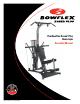
The Bowflex Xceed Plus Home Gym Assembly Manual ™ WWW BOWFLEX COM P/N 001-6907 Rev.
Congratulations on your commitment to fitness and your purchase of the Bowflex Xceed Plus home gym. Before assembling your Bowflex Xceed Plus home gym please read the Assembly Manual and follow the Important Safety Precautions. For information on how to use your Bowflex Xceed™ Plus home gym refer to the Bowflex Xceed™ Plus Owner’s Manual. ™ ™ Nautilus, Inc. 16400 S.E. Nautilus Drive Vancouver, Washington, USA 98683 1-800-NAUTILUS (1-800-628-8458) Fax (800) 898-9410 Nautilus.com Bowflex.
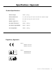
Specifications / Approvals Product Specifications: Product Weight 157 lbs. (71 kg) Product Dimensions 53" (135 cm) long x 49" (124 cm) wide x 82" (208 cm) high Workout Area 96" (244 cm) long x 78" (198 cm) wide Number of Exercises Over 60 Power Rod® Resistance 310 lbs. (141 kg) Power Rod® Upgradability 410 lbs. (186 kg.) User Weight Limit 300 lbs.
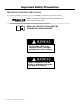
Important Safety Precautions IMPORTANT SAFETY INSTRUCTIONS The following definition applies to the word “Warning” found throughout this manual: 7! 2 . ) . ' $!.'%2 Used to call attention to POTENTIAL hazards that could result in personal injury or loss of life. Read all instructions before Assembling the machine. !4 4 % . 4 ) / . )--%$)!4% !#4)/. 2%15)2%$ #!54)/. For your safety, perform all assembly steps in the sequence given. Improper assembly can lead to injury.
Before You Begin Before You Assemble Basic Assembly Principles Please take the time to read all assembly instructions before attempting to assemble your Bowflex Xceed™ Plus home gym. Select where you are going to locate your machine carefully. The best place for your Bowflex Xceed™ Plus home gym is on a hard, level surface. Here are a few basic tips that will make your assembly of the Bowflex Xceed™ Plus home gym quick and easy.
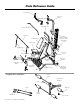
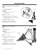
Parts Reference Guide ,AT #ROSS "AR 5PPER ,AT 4OWER ,EFT 0ULLEY !RM v "ENT ,AT "AR 3QUAT "AR 2OD "OX WITH 0OWER 2OD§ 2ESISTANCE 2ODS 3EAT "ACK 0AD 2IGHT 0ULLEY !RM 3EAT "OTTOM 3QUAT 3TRAPS ,OWER ,AT 4OWER 3EAT "ACKBONE ,EFT &RAME 2AIL 2EAR #ROSS -EMBER 3QUAT 0ULLEY &RAME "ASE &RAME 0LATFORM 2IGHT &RAME 2AIL Leg Extension Attachment 7RAPPED 3LIDER 0ULLEY WITH #ABLE #HROME 4UBES .
Parts Reference Guide Base Frame Left Frame Rail Right Frame Rail Lower Lat Tower Frame Rod Box w/ Rods Seat . Support . Rail Squat Pulley Frame Rear Cross . Member Left Pulley Arm Right Pulley Arm Cable Pulley Slider and Cable are included with pulley.
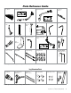
Hardware Guide Tools you will need: You will need the tools listed below to complete the assembly of your Bowflex Xceed™ Plus home gym. If you don’t have these tools, you can find them at any hardware or department store. • 7/16" Combination Wrench • 9/16" Combination Wrench • Adjustable Wrench • Socket Wrench Set • Phillips Screw Driver • Flat Blade Screw Driver • Rubber Mallet • Utility Knife • Scissors • A llen wrenches (included) (NOTE: Drawings not to scale.) Button Head Screws:.
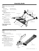
Assembly Guide Step 1 Base Frame Assembly Parts: • Base Frame • Left Frame Rail • R ight Frame Rail • Rear Cross Member Hardware: Button Head Screws • 6Button Head Screws ( 3/8" X 3/4") • 6Flat Washers (3/8") Flat Washers Left Frame Rail Tool: 7/32" Allen Wrench . Button Head Screws (or Hex Wrench) 1-1 Lay all parts on floor as Rear Cross Member Flat Washers shown. 1-2 Insert Frame Rail . connectors into the . Base Frame and . Rear Cross Member. .
Assembly Guide Step 3 Install Lower Lat Tower Assembly Parts: • Lower Lat Tower Assembly • Base Frame Assembly Lower Lat Tower Assembly Button Head Screw Hardware: • 2 Button Head Screws (3/8" X 3/4") • 2 Flat Washers (3/8") Button Head Screw Tool: 7/32” Hex Wrench Flat Washer 3-1 Align the Lower Lat Tower Assembly over . the Base Frame. Push the bottom of the Lower Lat Tower onto the connector of the Rear Cross Member as shown.
Assembly Guide Button Head Screws Step 5 Install Squat Pulley Frame Parts: • Squat Pulley Frame Assembly • Main Assembly Flat Washers Squat Pulley Frame Hardware: Flat Washers • 1Button Head Screw (3/8" X 5") • 1Nylock Nut (3/8") • 2Button Head Screws (3/8" X 1") • 4Washers (3/8") Nylock Nut Tools: 7/32" Hex Wrench & Adjustable . or Socket Wrench Button Head Screw 5-1 Place the Squat Pulley Frame behind the Seat Support Rail and align the top screw holes.
Assembly Guide Step 7 Secure Pulley Arms Hardware: • 2Threaded Studs (1/2" X 9 1/2") • 4Nylock Nuts (1/2") • 4Washers (1/2") Tool: Rubber Mallet Flat Washers Nylock Nuts 7-1 A lign the two holes in the Pulley Arms Flat Washers with those in the Lower Lat Tower Assembly and secure using threaded studs, washers and nuts as shown.
Assembly Guide Step 9 Seat Assembly Button Head Screws Parts: Flat Washers • Seat Backbone • Seat Bottom Hardware: • 4Button Head Screws (5/16" X 3/4") • 4Washers (5/16") Tool: 3/16" Hex Wrench 9-1 Install the Seat Backbone to the . Seat Backbone Seat Bottom underside of the Seat Pad using screws and washers as shown.
Assembly Guide Step 11 Install Optional . Leg Extension Assembly Lock Knob Parts: • Leg Extension Assembly • Lock Knob Leg Extension Backbone Seat Backbone 11-1 Insert Leg Extension Backbone into open end of Seat Backbone as shown. 11-2 A lign one hole of the Leg Extension with the hole in the Seat Backbone to fit your height and secure with the Lock Knob as shown.
Assembly Guide Step 13 Install Seat Back Pad Seat Back Pad Note: The back of the Seat Back Pad has two pairs of holes. Select the appropriate . set based on your height. Parts: • Seat Back Pad • Main Assembly Hardware: • 2Button Head Screws (5/16" X 2 1/2") • 2Washers (5/16") Tool: 3/16" Hex Wrench 13-1 Position Seat Back Pad against the . Flat Washers Button Head Screws Seat Support Rail and align the . screw holes for your height with . those on the Seat Support Rail.
Assembly Guide Step 15 Install Upper Lat Tower Assembly Parts: • Upper Lat Tower Assembly • Main Assembly Hardware (1:1): • 6Button Head Screws (3/8" X 3/4") • 6Washers (3/8") Tool: 7/32" Hex Wrench 15-1 Position the Upper Lat Tower Assembly . over the Lower Lat Tower Assembly. 15-2 Slide the Upper Lat Tower onto the . Lower Lat Tower and secure with screws . and washers as shown.
Assembly Guide Step 17 Connect Cables Parts: Completed Bowflex Xceed™ Plus home gym Tool: Scissors or other cutting tool 17-1 Remove the wrapping from around the coiled cable and pulley attached to the Right and Left Frame Rails. 17-2 Removethe wrapping from around the coiled cable and pulley attached to the left and right side of the lat tower. 17-3 Attach the cable to the home gym following the routing for the various exercise positions.
Assembly Guide Step 18 Final Inspection Please inspect your machine to ensure that all fasteners are tight and components are properly assembled. Review all warnings affixed to machine. Congratulations! You have successfully completed assembly of your Bowflex Xceed™ Plus home gym! Failure to visually check and test assembly before use can cause damage to the Bowflex Xceed™ Plus home gym and serious injury to users and bystanders and can also compromise the effectiveness of your exercise program.
Important Contact Numbers If you need assistance, please have both the serial number of your machine and the date of purchase available when you contact the appropriate Nautilus office listed below. Please record the following information for future reference. Serial Number Date of Purchase OFFICES IN THE UNITED STATES: • TECHNICAL/CUSTOMER SERVICE Nautilus, Inc.
© 2007 Nautilus, Inc. All Rights Reserved. Nautilus, Inc. World Headquarters, 16400 S.E. Nautilus Drive, Vancouver, Washington USA 98683 1-800-NAUTILUS (1-800-628-8458) Bowflex, Bowflex Xceed, Power Rod and the Bowflex logo are either registered trademarks or trademarks of Nautilus, Inc. All other trademarks are trademarks of their respective companies.