Z_CAL 150 300 MODE D’EMPLOI INSTRUCTIONS FOR USE GEBRAUCHSANLEITUNG Sylvac SA Ch.
1.
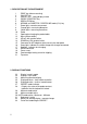
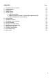
CONTENTS 1. 2. 3. 4. 5. 6. 7. 8. 9. 10. 11. 12. 13. 14. 15. Description of the instrument Display functions Introduction Getting started How to start up 5.1 Measuring heights 5.2 Measuring reverse surfaces - Measuring the probe constant 5.
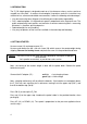
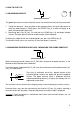
3. INTRODUCTION The Z_CAL height gauge is designed to work on a flat reference surface, such as granite or scraped cast iron plate... A number of technological innovations make this instrument very suitable for fast, accurate and reliable measurements. It offers the following main advantages : • Very low measuring force (30 grams) for delicate parts and excellent repeatability. • Fully motorized probe. Its displacement speed is proportional to the finger pressure.
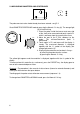
. HOW TO START UP Normal 5.1 MEASURING HEIGHTS ref The green light comes on when the probe comes into contact with the part being measured. 1. Taking the reference : drive the probe to the reference plane, the green light comes on when the probe touches it. Briefly press the PRESET key (3) to zero the display or to recall the memorized Preset value. 2. Measuring: press the UP key (13) and then the DOWN key (14) and probe another surface. The green light will come on and the height will be displayed.
5.3 MEASURING DIAMETERS AND CENTERLINES ∅ ⊕ The probe constant value should already have been entered : see § 5.2. Go to DIAMETER/CENTERLINE mode by pressing the Normal ∅ ⊕ key (6). The orange light (8) will start flashing. 1. Place the probe inside the bore or onto one side of the shaft to be measured and touch a point P1 which is well away from the summit of the curve. P2 2. Move the part or the Z_CAL sideways to the P1 P1 probe. The minimum/maximum point is memorized. 3.
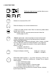
6. MAIN FUNCTIONS Briefly pressing these keys provides direct access to each function. On/Off Switches the instrument ON or OFF. Preset Zeroes the display or sets to the memorized value. - Displays the probe constant value. Return to measuring mode without change : press any key. - Measuring the constant : one measurement on each side of the master gauge (see 5.2).
7. SECONDARY FUNCTIONS Access by long pressure on the keys mm/in : Direct conversion of mm ↔ inches. To lock or unlock the conversion: switch the instrument on while pressing the Resol key. Ref I/II : Change of reference. For example: - Reference 1 with Preset = 0.000 mm - Reference 2 with Preset = 100.
8. AC ADAPTER, EXTERNAL CONTACT B If the indicator (32) showing complete battery discharge is displayed, connect the AC adapter. The instrument remains operational. Complete recharging takes 4 hours. A foot pedal may be connected to the external contact (15) for data transfer. Another function may be assigned to it (see § 6, Print key). 9. RS232 CONNECTOR The RS232-C port (18) is OptoRS compatible (see OptoRS convention for more informations).
Remote control of the Z_CAL : The instrument functions are controlled externally by an ASCII code corresponding to the 3 first letters of the function. Spaces are removed. The message may be in upper or lower case. The question mark ? implies an instrument response. ? or PRI (PRInt) requests displayed value CLE (CLEar) EXT0 EXT1 EXT2 EXT3 EXT? (EXTernal contact) EXTB...
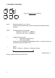
10. CHANGING THE PROBE HOLDER To change the probe holder, raise the probe using the UP key (13) to the upper stop. Remove it while pushing it up. Introduce the new probe holder Turn correctly the eccentric probes. Clamp firmly but do not force, using the 2.5 mm imbus key. Make sure to keep the same weight (for the part probe + the probe holder) while using other probes : 2 oz ± 0.5 oz (refer to the indications provided with the set of probe holders). The probe constant must be measured, see chapter 5.2.
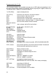
13. TECHNICAL SPECIFICATIONS Z_CAL 150 Z_CAL 300 Measuring range Total measuring range 150 mm 155 mm 300 mm 320 mm Resolution Accuracy (precision) with std probe at stop Repeatability ±2 s 0.00005 in (1 µm) 0.00015 in (4 µm) 0.00008 in (2 µm) 0.0002 in (5 µm) Probe max speed Motor max speed Measuring force (set at works) Measuring range of measuring force Operation time 3 m/s 0.1 m/s 0.3 N (1 oz) 0.25 N…0.5 N (0.9 … 1.8 oz) 40 hours approx.
15. ACCESSORIES Item No. - Set No. 1 with special probes in a wooden case comprising : 930.2151 - 1 probe with saphire ball , ∅ 2 mm - 1 probe, ∅ 1 mm / M1.4 and tightening spanner - 1 probe with bevelled anvil in hard metal - 1 probe with rounded anvil ∅ 3 x 5 mm to measure threads Note : all these probes weigh 7 grams and therefore require no rebalancing of the measuring force. - Set No. 2 with special probes in a wooden case comprising : - in addition to the above set nr 930.