
Owner`s manual


29843-5-1012Page 8
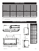
Mantel Chart
A 20"(508mm) J 17-1/2"(444mm)
B 21-1/2"(546mm) K 17"(431mm)
C 13-1/2"(343mm) L 16-1/2"(419mm)
D 12"(305mm) M 16"(406mm)
E 20-1/2"(521mm) N 15-1/2"(394mm)
F 19-1/2"(495mm) O 15"(381mm)
G 19"(482mm) P 14-1/2"(368mm)
H 18-1/2"(469mm) Q 14"(356mm)
I 18"(457mm) R 13"(330mm)
Figure 4
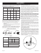
Ceiling Height and Side Wall Clearances
Minimumceilingheightis 46"(116.8cm)
Clearancefromsideofreplacetoadjacentsidewallis2"(51mm).
Note:Somedecorativefrontsrequiremorethan2"clearancedue
tofrontsize.
▲
►
▼
◄
21-1/2”
()546mm
MINIMUM
2”
()51mm
Figure 5
CLEARANCES
Clearance to Combustibles - Shown in inches (metric)
Back 1-1/4(32mm)
Side 3-1/8(79mm)
Floor 0(0mm)
TopStand-off 12(305mm)
TopFramingEdge 12(305mm)
MinimumHeightFloorToCeiling 45-3/4(116.2cm)
IN THIS AREA
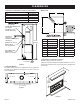
HEADER RECOMMENDATION:
USE DOUBLE
HEADER OR PLACE
HEADER VERTICALLY
SEE MANTEL
CHART FOR
MAXIMUM MANTEL DEPTH
AND HEIGHT
57-7/16”
(145.0cm)
STANDOFF 12” (305mm)
HEIGHT ABOUT
TOP OF FIREPLACE
NON-COMBUSTIBLE
FINISHED WALL
FIRST 13-1/2” (343mm)
1-1/4” (32mm)
►
▲
▼
◄
▲
▲
▼
▼
▲
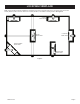
Figure 2
Combustible Material
Nogreetingcards,stockingsorornamentationofanytypeshould
be placed on or attached to the replace. The ow of heat can
ignitecombustibles.
ONLY NON-COMBUSTIBLE MATERIALS
ALLOWED OVER THE FIREPLACE FACE
ON EACH SIDE
3-1/8” (79mm)
3-1/8” (79mm)
1-1/4” (3mm)
Figure 3