
Owner`s manual


29843-5-1012Page 28
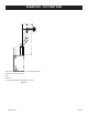
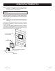
VERTICAL TERMINATION
Locateandmarkthecenterpointoftheventingpipe.Usinganail
ontheundersideoftheroofanddrivethisnailthroughthiscenter
point.Maketheoutlineoftheroofholearoundthiscenterpoint.
NOTE: Sizeoftheroofholedimensionsdependonthepitchof
theroof.Theremustbea1inchclearance(25mm)tothe
verticalpipesections.Thisclearanceistoallcombustible
material.
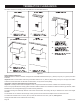
Covertheopeningoftheventpipeandcutandframetheroofhole.
Useframinglumberthesamesizeastheroofraftersandinstallthe
framesecurely.Flashinganchoredtoframemustwithstandhigh
winds.Thestormcollarisplacedoverthisjointtomakeawater-tight
seal.Non-hardeningsealantshouldbeusedtocompletelysealthis
ashinginstallation.
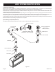
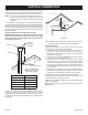
Determining Minimum Vent Height Above the Roof.
WARNING: Major U.S. building codes specify minimum chimney
and/or vent height above the roof top. These minimum heights
are necessary in the interest of safety. These specications are
summarized in Figure 40.
H
X
12
▲
▼
◄
▼
▼
◄
VENT CAP
GAS VENT
LOWEST
DISCHARGE
OPENING
ROOF PITCH IS X/12
H (MIN.) = MINIMUM HEIGHT
FROM ROOF TO LOWEST
DISCHARGE OPENING
ROOF PITCH H(Min.)
Flatto6/12 12in.(305mm)
6/12to7/12 15in.(381mm)
Over7/12to8/12 18in.(457mm)
Over8/12to16/12 24in.(610mm)
Over16/12to21/12 36in.(914mm)
Figure 40
Notethatforsteeproofpitches,theventheightmustbeincreased.
Inhigh windconditions,nearbytrees, adjoiningrooflines, steep
pitchedroofs,andothersimilarfactorscanresultinpoordraft,or
down-drafting.Inthesecases,increasingtheventheightmaysolve
thisproblem.
◄
▲
◄
▼
►
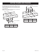
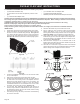
24” MIN.
(609.6mm)
►
24” MIN.
(609.6mm)
12” MIN.
(304.8mm)
Figure 41
Whenterminatingtheventcapnearanexteriorwalloroverhang,
maintainminimumclearancesasshowninFigure 41.
General Maintenance
Conduct an inspection of the venting system semi-annually.
Recommendedareastoinspectareasfollows:
1. Checkareasoftheventingsystemwhichareexposedtothe
elements for corrosion. These will appear as rust spots or
streaksand,inextremecases,holes.Thesecomponentsshould
immediatelybereplaced.
2. Removethecapandshineaashlightdownthevent.Remove
anybirdnestsorotherforeignmaterial.
3. Check for evidence of excessive condensate, such as water
droplets forming in the inner liner and subsequently dripping
outatjoints.Condensatecancausecorrosionofcaps,pipeand
ttings.Itmaybecausedbyhavingexcessivelateralruns,too
manyelbowsandexteriorportionsofthesystembeingexposed
tocoldweather.
4. Inspectjointstoverifythatnopipesectionsorttingshavebeen
disturbedand,consequently,loosened.Also,checkmechanical
supports,suchaswallstrapsorplumbers’tapeforrigidity.
Ventingterminalshallnotberecessedintoawallorsiding.
Aremovablepanelorothermeansmustbeprovidedintheenclosure
forvisualinspectionoftheueconnection.
NOTE:Thisalsopertainstoverticalventsystemsinstalledonthe
outsideofthebuilding.
Slidetheverticalventcapovertheendsoftheventpipeandsecure.
See Figure 41.