
Owner`s manual


29843-5-1012 Page 25
A
B
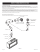
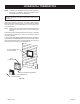
WALL FIRESTOP HOLE IS OFF-SET
TOWARDS BOTTOM OF WALL OPENING
►
▲
▼
◄
▲
Vent Size A B
6-5/8in.
(168.3mm)
12-3/8in
(314.3mm).
12-3/8in.
(314.3mm)
Figure 35
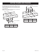
Verticalrunsofthissystemwhichpassthroughceilingsrequirethe
useofONE(1)ceilingrestopattheholeineachceilingthrough
whichtheventpasses.
Positionaplumbbobdirectlyoverthecenteroftheverticalvent
componentandmarktheceilingtoestablishthecenterpointofthe
vent.Drillaholeordriveanailthroughthiscenterpointandcheck
the oor above for any obstructions such as wiring or plumbing
runs.Repositiontheapplianceandventsystem,ifnecessary,to
accommodateceilingjoistsand/orobstructions.
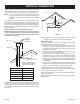
Cutanappropriatesizedholethroughtheceiling,usingthecenter
pointpreviouslymarked.See Figure 36.Frametheholewithframing
lumberthesamesizeastheceilingjoists.See Figure 36.
B
A
▲
►
▼
◄
◄
▲
▲
►
►
►
EXISTING CEILING JOISTS
NEW FRAMING
CEILING BELOW
Vent Size A B
6-5/8in.
(168.3mm)
9-1/2in.
(241.3mm)
9-1/2in.
(241.3mm)
Figure 36
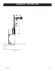
Installing Support Brackets
A horizontal pipe support MUST BE used for each 3 feet of
horizontalrun.Thepipesupportsshouldbeplacedaroundthepipe
andnailedinplacetoframingmembers.ThereMUSTBEa3inch
clearancetocombustiblesaboveuepipeandelbowsand1inch
clearanceonbothsidesandbottomoftheuepipetocombustibles
onallhorizontalpipesectionsandelbows.
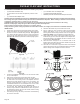
Verticalrunsofthisventsystemsmustbesupportedevery4feet
abovethe appliance ue outlet by wall brackets attached to the
ventpipeandsecured with nails or screws to structuralframing
members.
▲
►
▼
◄
◄
◄
PIPE STRAP
48”
(121.9cm)
►
STUD WALL
► ◄
1” MIN.
(25.4mm)
1-1/4” MIN.
(32.7mm)
FLUE
OUTLET
Figure 34
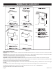
Installing Firestops
Firestopsarerequiredforsafetywhenevertheventsystempasses
throughaninteriorwall,anexteriorwall,oraceiling.Theserestops
actasarebreakheatshieldandasameanstoinsurethatminimum
clearancesaremaintainedtotheventsystem.
Horizontalrunsintheventsystemwhichpassthrougheitherinterior
orexteriorwalls,requiretheuseofwallrestopsonbothsidesof
thewallthroughwhichtheventpasses.
Cut an appropriate sized hole in wall. See Figure 35. Position
restoponinteriorsideofwallforhole.
Attention: Wall restop hole is off-set towards bottom of wall
opening.Securewithnailsorscrews.Continuetheventrunthrough
therestop.See Figure 35.
Attention: Horizontal venting through a wall requires a wall
thimbleontheinteriorsideofthewallabovethepipe.
VENTING FRAMING AND FINISHING