
Owner`s manual


29843-5-1012 Page 19
◄
▲
▼
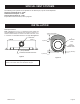
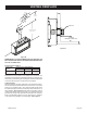
VENT CAP
9” (229mm)
MINIMUM TO SIDE WALL
Figure 27
VENTING FIREPLACE
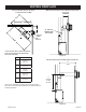
10”
(254mm)
12”
(305mm)
A
CENTER OF FRAMING
(MINIMUM VENT)
V
CENTER
OF ELBOW
H
C
B
C
B
Figure 26
MINIMUM HOLE LOCATION DIMENSIONS FOR THROUGH THE
WALL HORIZONTAL INSTALLATIONS WITH 90 DEGREE ELBOW
OFF TOP OF FIREPLACE
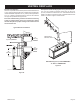
Positioning the Fireplace
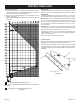
FIREPLACE
SERIES
HARD ELBOW DIMENSIONS
A B C
DVLL/DVTL
55-5/8in.
(141.3cm)
5in.
(127mm)
7in.
(178mm)
Determinetheexactposition of the appliance so the direct vent
terminationwillbecentered(ifpossible)betweentwo(2)studs.This
willavoidanyextraframing.Allventkitpipesshouldbeassembled
ontheunitaftertheunitismovedintothenalposition.
Cutting the Hole
Afterthereplacehasbeenpositionedinitspermanentlocation,
theholethroughtheexteriorwallofthehousecanbecut.Thishole
mustbe12in.(305mm)highx10in.(254mm)widewithitscenter
linedeterminedbytheamountofverticalriseandhorizontalrunof
thetermination.See Figure 26. Whenlocatingtheholeitmustbe
notedthatthebottomofthecapmustbe12in.(305mm)abovethe
groundlevel,andtopofthecapmustbenolessthan18in.(457mm)
belowacombustibleprojection,andnocloserthan9in.(229mm)
toanywallrunningparalleltoventtermination.See Figure 27.