
Owner`s manual


29843-5-1012 Page 17
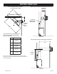
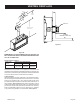
Example Of Possible Venting System Using One 90° Elbow
8 ft. (2.44 m) is listed as minimum vertical vent run with 20 ft.
(6.10m)ofmaximumhorizontalventrun.Verticaldimensionsare
basedoncenterlinetocenterlineofpipe.Horizontaldimensionsare
basedoncenterlineofpipetoexteriorofwall.
▲
▼
▲
▲
▲
FIRESTOP AT
CEILING LEVEL
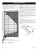
SEE GRAPH (Figure 21) FOR PERMISSIBLE
"H" AND "V" DIMENSIONS
Figure 24
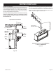
Below Grade Installation
Whenitisnotpossibletomeettherequiredventterminalclearances
of12in.(305mm)abovegradelevel,asnorkelkitisrecommended.
Itallowsinstallationdepthdownto7in.(178mm)belowgradelevel.
The7in.(178mm)ismeasuredfromthecenterofthehorizontal
ventpipeasitpenetratesthroughthewall.
Ensure the sidewall venting clearances are observed. If venting
system is installed below ground, we recommend a window
well with adequate and proper drainage to be installed around
the termination area.
Typical Basement Installation
►
▼
▼
▲
▲
3” (76 mm) MINIMUM
▲
▼
18”
(457 mm)
MINIMUM
▲
▼
12”
(305 mm)
ABOVE
GRADE
48”
(121.9cm)
Figure 23
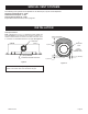
VENTING FIREPLACE