
Owner`s manual


29843-5-1012Page 14
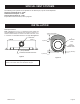
Attention: Cold climate installation recommendation:
When installing this unit against a non-insulated exterior
wall, it is recommended that the outer walls be insulated to
conform to applicable insulation codes.
Vent Runs
Inplanningtheinstallationforthereplace,itisnecessarytoinstall
certaincomponentsbeforetheapplianceiscompletelypositioned
andinstalled.Theseincludethedirectventsystem,gaspipingfor
theapplianceandtheelectricalwiring.
Theappliancecanbemountedonanyofthefollowingsurfaces:
1. Aat,hardcombustiblesurface.
2. Araisedwoodenplatform.
3. Four(4)cornersupports.(Example:Four(4)concretemasonry
blocks.)Thesesupportsmustbepositionedsotheycontactall
four(4)perimeteredgesonthebottomoftheunitandunderthe
centerlegsupports.Twomoresupportsspacedevenlyforfront
andbackmayberequiredpendinglocalcode.
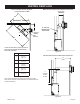
Vertical, 90° Elbow With Horizontal Termination
▼
◄
◄
▲
▼
▲
3” (76mm)
MINIMUM CLEARANCE
TO COMBUSTIBLES
61-5/8”
(156.52cm)
VENT CAP/
THIMBLE
WALL
FIRESTOP
Figure 16
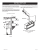
IMPORTANT:
MINIMUM HEIGHT OFF THE TOP REQUIREMENTS
DVLL & DVLT -MUSTUSEa2ft.(610mm)verticalventpipeas
therstsectionBEFOREinstallingtheelbow.
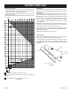
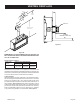
Vertical, 90° Elbow To
Horizontal Out The Wall
◄
►◄
►
◄
◄
90°
ELBOW
VENT
CAP
WALL
FIRESTOP
A
PIPE LENGTH
B
C
A B C
6in.
11-3/4in.to12-3/4in.
(298mmto323mm)
4-3/4in.to6-1/4in.
(121mmto159mm)
9in.
14-1/4in.to15-3/4in.
(362mmto400mm)
7-3/4in.to9-1/4in.
(197mmto235mm)
12in.
17-1/4in.to18-3/4in.
(438mmto476mm)
10-3/4in.to12-1/4in.
(273mmto311mm)
Figure 17
VENTING FIREPLACE