Owner’s Manual Main features Pedalboard Integration Evolved 55 Integrated system with versatile built-in effects plus three loops for your favorite pedals. 55 Space-saving design enables you to create a compact pedalboard with sophisticated functionality. 55 Advanced control and expandability delivers infinite creative possibilities. Owner’s Manual (this document) Read this first. It explains the basic things you need to know in order to use the MS-3.
Contents Getting Ready . . . . . . . . . . . . . . . . . . . . . . . . 3 Rear Panel (Connecting Your Equipment). . . . . . . . . 3 Top Panel. . . . . . . . . . . . . . . . . . . . . . . . . . . 5 Screen Structure . . . . . . . . . . . . . . . . . . . . 6 Operation of the [1]–[3] Knobs. . . . . . . . 7 Switching Pages. . . . . . . . . . . . . . . . . . . . . 7 Turning On/Off the Power. . . . . . . . . . . . 8 Tuning the Guitar (TUNER). . . . . . . . . . . . 8 Playing . . . . . . . . . . . . .
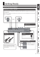
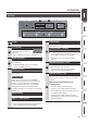
Getting Ready Rear Panel (Connecting Your Equipment) LOOPS jacks (L1–3 SEND, L1–3 RETURN) These jacks provide effect loops. The MS-3 is equipped with three loops: L1–3. Signals are sent from L1–3 SEND jacks to each effect unit, and the signals from each effect unit are received at the L1–3 RETURN jacks. Connect the L1–3 SEND jacks to the INPUT jack of each effect unit, and connect the OUTPUT jack of each effect unit to the L1–3 RETURN jacks.
Getting Ready Rear Panel (Connecting Your Equipment) CTL OUT jack (CTL 1/2) MIDI OUT connector You can connect this jack to the control jack of your external device. It can be used to control things such as switching channels of an amp, turning reverb on/off, or setting tap tempo. By using a TRS plug with this jack, you can separately control two targets (TIP: CTL 1, RING: CTL 2). You can connect this to a MIDI-compatible effect unit and control it from the MS-3.
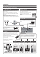
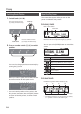
Getting Ready Top Panel 2 1 4 5 3 6 1 Display [EXIT] button The MS-3 shows various information here. Press this to cancel an operation, or to return to the previous screen. [1]–[3] knobs 2 Use these to select or edit the values of parameters shown in the screen. [ENTER] ([PAGE >])button [1] [2] [3] 4 55 In screens that show page tabs, this operates as the [PAGE >] button to switch pages. * Refer to “Operation of the [1]–[3] Knobs” (p. 7).
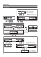
Getting Ready Screen Structure System settings (p. 15) Use the [< PAGE] [PAGE >] buttons to change pages Use the [1]–[3] knobs to move the cursor WRITE UTILITY screen (p. 13) MENU screen (p. 15) Play screen (p. 10) Memory mode Tuner screen (p. 8) MEMORY/MANUAL Manual mode MUTE & TUNER Hold for two seconds Patch edit (p. 11) Effect chain screen (p. 12) Use the [1]–[3] knobs to move the cursor CTL, ASSIGN & MIDI SETTING screen (p.
Getting Ready Operation of the [1]–[3] Knobs 55 When function names or parameters are shown in the lower line of the display, the [1]–[3] knobs correspond to those functions or parameters. [1] [2] [3] 55 In the CTL, ASSIGN & MIDI SETTING screen (p. 12), the WRITE UTILITY screen (p. 13), and the MENU screen (p. 15), you can operate any knob to move the cursor and select an icon. [1] [2] [3] 55 In screens where knob or switch icons are shown, the [1]–[3] knobs correspond to those icons.
Getting Ready Turning On/Off the Power * Before turning the unit on/off, always be sure to turn the volume down. Even with the volume turned down, you might hear some sound when switching the unit on/off. However, this is normal and does not indicate a malfunction. When powering up Turn on the power in the following order: this unit ([POWER] switch: ON) 0 connected equipment 0 guitar amp.
Playing Patch Structure A “patch” consists of a combination of settings for the MS-3’s built-in effects and the effect loops (L1–3). A set of four patches is called a “bank.” Patches are managed by their bank (1–50) and number (1–4); the MS-3 can store 200 patches.
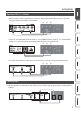
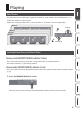
Playing Switching Banks/Patches About the Play Screen 1. Switch banks (01–50). The screen that appears after you turn on the power is called the “Play screen.” Press the number switch [3] and [4] simultaneously. Bank up In memory mode Bank – Patch number Patch name [1] Bank down Press the number switch [1] and [2] simultaneously. 2. Press a number switch [1]–[4] to switch patches.
Editing the Settings of a Patch Basic Operation Icon 1. Recall the patch that you want to edit (p. 10). 2. Press the [EDIT] button. – Explanation Choose from a variety of effect types. You can also choose the same effect for FX1 and FX2. Choose from various types of modulation effect. You can also choose the same effect for MOD1 and MOD2. Turn loop effects on/off. Choose from various types of delay. The effect chain screen appears. Choose from various types of reverb.
Editing the Settings of a Patch MEMO Pressing the [ON/OFF] button in the edit screen switches the effect’s on/off status. This lets you hear what the effect is doing. When tabs are displayed on the screen, you can switch pages by pressing the [< PAGE] [PAGE >] buttons. 2. Use the [2] knob to move the selected effect. Changing the CTL/ASSIGN/MIDI Settings For each patch, you can make CTL, ASSIGN, and MIDI settings to operate a variety of parameters. 5.
Editing the Settings of a Patch Icon Explanation Saving a Patch – Specify the parameters that are controlled by footswitches (CTL 1–4) connected to the CTL IN jacks. – ASSIGN lets you make more detailed settings. For example, use ASSIGN if you want another parameter to also be operated at the same time in addition to the parameter operation of number switch [1]. You can make eight settings for each patch. If you want to save the patch that you created, execute the Write operation.
Editing the Settings of a Patch 4. To save the patch, press the [ENTER] Initializing a Patch * If you decide to cancel, press the [EXIT] button. Here’s how to return the selected patch to the default values. button. Once the patch has been saved, you are returned to the Play screen. 1. In the WRITE UTILITY screen, choose “INITIALIZE” with the [1]–[3] knobs, and press the [ENTER] button. Exchanging Patches 2. Choose the initialize-destination patch with the [1] knob.
System Settings (MENU) Settings that are shared by the entire MS-3 are called “system settings.” For details on the parameter, refer to the “Parameter Guide” (PDF file). Icon Explanation Refer to “Enabling/Disabling the AutoOff Function” (p. 16). Refer to “Restoring the Factory Default Settings (Factory Reset)” (p. 16). Press the [ENTER] button to enter the edit screen. Basic Operation 1. Press the [MENU] button.
System Settings (MENU) Enabling/Disabling the Auto-Off Function If you set the auto-off function to “On,” the power will turn off automatically when 10 hours have passed since you last played or operated the unit. The display will show a message approximately 15 minutes before the power turns off. * With the factory settings, this function is turned “On.” If you want to have the power remain on all the time, turn it “OFF.” 1.
Using a Computer to Edit/Back up Patches By connecting the MS-3 to a computer via USB, using the dedicated software allows you to do the following: 55 Edit patch settings 55 Name patches 55 Organize patches in order and switch them around 55 Back up patches and system settings, and return to the backed up settings 55 Display the “Parameter Guide,” “Application Guide,” and “MIDI Implementation” (PDF file) on your computer Installing the USB Driver You must install the USB driver before connecting to a com
Appendix Error Messages Display USB OFFLINE! DATA WRITE ERROR! LOCKED! Problem Transmissions from the connected device have been interrupted. This message also appears when the power to the connected device has been turned off. It does not indicate damage. Writing to the memory for storage of user data failed. The [1]–[3] knobs and buttons are locked. Action Check to make sure no cable is disconnected and that there are no shorts. The unit may be damaged. Consult the nearest Roland service center.
Appendix Main Specifications BOSS MS-3: Multi Effects Switcher Modes Memory mode/Manual mode Loops 3 24 bits + AF method AD Conversion AF method (Adaptive Focus method) This is a proprietary method from Roland & BOSS that vastly improves the signal-to-noise (SN) ratio of the AD and DA converters. DA Conversion Sampling Frequency Effects Patches 24 bits 44.
USING THE UNIT SAFELY WARNING Concerning the Auto Off function The power to this unit will be turned off automatically after a predetermined amount of time has passed since it was last used for playing music, or its buttons or controls were operated (Auto Off function). If you do not want the power to be turned off automatically, disengage the Auto Off function (p. 16).