
Specifications


16
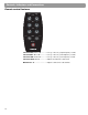
Controls, Indicators, and Connections
Channel 1/2 connections and controls
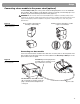
Input ..........................................Combination XLR (mic) or ¼-inch TRS (Line) input jack.
Inserting a male XLR connector sends the input signal to a
balanced microphone preamplifier. Inserting a ¼-inch phone
connector sends the input signal to an unbalanced high-
impedance line-level circuit which is suitable for most instru
-
ments such as active or passive guitars or basses, key-
boards, etc. Both inputs can be adjusted with the Trim
control.
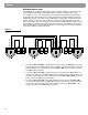
Mic Trim 0 to 12 ........................Controls the microphone input level.
Signal/OL ..................................Indicates signal presence (green) or signal overload (red).
Phantom Off/+24V....................When depressed turns on the +24V phantom power. The
LED lights when phantom power is on.
Preset Select ............................Selects a comprehensive channel equalization, which results
in a “normal” or useful sound when the product is used with
commonly available equipment such as microphones, musi
-
cal instruments or sound processors. The selectable settings
from 00 to 99 apply only to channel and 2. Settings are iden
-
tical on both channels but are independently selected. See
the Presets Guide included in the power stand carton.
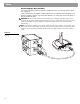
Line OUT ...................................XLR output for sending to external recording equipment.
Insert .........................................A TRS line input/output for connecting to external equip-
ment. Plug inserted halfway connects to “Send”; inserted
fully connects to “Return”.
Note: Use a stereo plug in the Insert jack for connecting send and return signals.
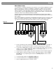
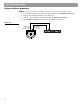
Channel 3/4 connections and controls
Line IN .......................................A ¼-inch phone connector line input for external equipment.
Level 0 to 12..............................Controls the source input level.
Unbal
Unbal