Bose® FreeSpace® Model 8 And Model 32 Loudspeakers Installer’s Guide May 6, 2002 AM177915_03_V.
1.0 Safety Information Please read this guide Bose® FreeSpace® Model 8 and Model 32 loudspeakers are significantly different from conventional ceiling loudspeakers, both in operation and installation. We recommend this guide be read carefully. Safety Information 1.1 Read the instructions – Read and keep all safety and operating instructions. 1.2 Follow cautions – For safety, follow all cautions and warnings in this guide and on the loudspeakers. 1.
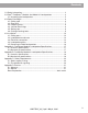
Contents 1.0 Safety Information ....................................................................................... 2 2.0 Bose® FreeSpace® Model 8 And Model 32 Loudspeakers ......................... 4 2.1 Unpacking the loudspeakers ................................................................ 5 3.0 Before You Begin ........................................................................................ 6 3.1 Ceiling type ...............................................................................
2.0 Bose® FreeSpace® Model 8 And Model 32 Loudspeakers Bose designed the FreeSpace Model 8 and Model 32 loudspeakers to provide high fidelity voice and music reinforcement in commercial settings. These Virtually Invisible® loudspeakers meet the aesthetic demands of most architectural designs. The loudspeaker rim and grille can be painted to match the setting. Bose has an information sheet explaining how to paint the rim and grille. Call 1-800-996-BOSE and ask for a copy of 183073 Loudspeaker Painting.
2.0 Bose® FreeSpace® Model 8 And Model 32 Loudspeakers All versions meet all regulatory standards for ceiling loudspeakers and are UL listed as vandal resistant. A 70V fire safety version of each model, available only by special order, is also UL listed as a fire protective signaling device. Complete safety agency listings and special requirements for fire protective signaling and warning systems are contained in Appendix C, “Safety Requirements.
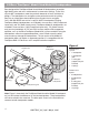
3.0 Before You Begin 3.1 Ceiling type Evaluate the ceiling construction BEFORE beginning installation. Ceiling type, thickness, and strength determine the installation and connection methods as well as the necessity of support rails. A qualified person, such as a building trade professional, architect, or licensed professional engineer, should make these determinations. Bracket installation This guide covers installation methods for both ceiling tile and structural ceilings.
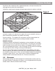
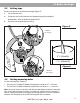
3.0 Before You Begin For 625 mm tiles, extend the rails in opposite directions until each rail reaches the ceiling grid on one side of the mounting pan. Ceiling tiles made of particle board, plywood, gypsum board, or plaster usually do Figure 2 10°– 15° not require support rails. However the support rails may be needed if moisture or other environmental conditions may weaken the ceiling.
3.0 Before You Begin 3.3 Preparing wires Figure 3 70V and 100V versions The loudspeaker terminals will accept either stripped wires or crimp-on forked connectors. Note: Using forked connectors for multiple wires is not acceptable in fire protective signaling and warning systems due to the lack of electrical supervision capability. Prepare the wires as shown (Figure 3). • For bare wire connections, strip the wires to 3/8" – 7/16" (9 – 10 mm). • For crimp-on connectors, strip the wires to 5/16" (8 mm).
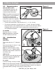
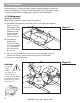
3.0 Before You Begin 3.5 Setting taps Set the transformer to the preferred wattage (Figure 5): 1. Locate the blue wire. 2. Disconnect the smaller tab from the shipped setting (8W on Model 8 loudspeakers, 32W on Model 32 loudspeakers). 3. Reconnect to the preferred tap setting. Figure 5 Model 8 tap settings – C 4 8 + 2 70V 1 16 32 – 2 C 4 8 + 70V 1 5 3/4" (Model 8) 7 3/16" (Model 32) Figure 6 – 2 C 4 8 + 70V 1 16 32 3.
4.0 Installation Review Section 3.0 “Before You Begin” before installing FreeSpace® Model 8 or Model 32 loudspeakers. It contains important guidelines for choosing the correct installation method and providing proper support for the loudspeakers. 4.1 Ceiling pans Ceiling tile installation Note: Do not unhook the springs. Wear safety glasses. 1a. For Model 8 loudspeakers, push both halves of the ceiling pan together (Figure 7).
4.0 Installation Figure 9 4. Place the ceiling pan over the hole in the ceiling tile (Figure 9). ;;;;; ;;;;; ;;;;; Note: For 2' x 4' ceiling tiles, place the rails parallel with the 2 foot side of the tile. 5. Pull the springs through the mounting hole and hook in the installation position shown (Figure 10). Note: Complete electrical connections now or use the rotation feature after installing the loudspeakers. See Section 4.3, “Electrical connections.” Figure 10 AM177915_03_V.
4.0 Installation Structural ceiling installation Before beginning this method of installation see Section 3.1, “Ceiling type” to be sure the ceiling qualifies for installation as a structural ceiling. Note: Do not unhook the springs. Wear safety glasses. 1. For both FreeSpace® 6 Model 8 and Model 32 loudspeakers, remove the rails from the ceiling pans (Figure 11). The ceiling pan will not fit through the mounting hole with the rails installed.
;;;;; ;;;;;;;;;; ;;;;;;;;;; ;;;;; ;;;;; ;;;;; ;;;;; 4.0 Installation Figure 13 Figure 14 4.2 Loudspeaker enclosures Note: If the electrical connections have not been made yet, pull all wires through the mounting hole and clear of the springs. Figure 15 Complete electrical connections before releasing the loudspeaker into the ceiling. Releasing the loudspeaker with wires unconnected could cause the loudspeaker to jam on the dangling wires and could damage the mounting hole or the loudspeaker rim.
4.0 Installation 4.3 Electrical connections Figures 18a and 18b Figure 18a 70V and 100V versions 1a. For stripped wire connections, place one straight wire on each side of the screw beneath the screw plate. Tighten the screw (Figure 18a). 1b. For crimp-on forked connectors, slide the connector under the screw plate. Tighten the screw (Figure 18b).
4.0 Installation Rotation feature The rotation feature provides access to the loudspeaker terminals during or after installation. This feature can be used for extra support while completing electrical connections or changing tap settings. The rotation feature is not an option if the ceiling is very thick or the tiles are very soft. See the guidelines in Section 3.1, “Ceiling type.” If the rotation feature is used, be careful not to damage the edge of the mounting hole or the loudspeaker rim.
4.0 Installation 4.4 Loudspeaker grilles ;;; ;;; 1. Pull down on the tab to remove the paint shield (Figure 23). 2. Push up on the grille until it is flush with the loudspeaker rim (Figure 24). Note: If the ceiling tile lifts up as the grille is installed, pull the loudspeaker down slightly. Hold the loudspeaker rim firmly with your fingers while pushing up on the grille with your thumbs. Note: It is not necessary to orient the Bose® logo before installing the grille.
Appendix A: FreeSpace® Model 8 Loudspeaker Specifications A.1 Acoustic specifications Sensitivity: 70V & 100V – 81dB 1W 1m, maximum 90dB 8W 1m Sound pressure level (SPL) sensitivity is measured in an anechoic chamber as follows: • Full bandwidth pink noise is applied through a Model 8 equalizer and fed into a power amplifier.
Appendix B: FreeSpace® Model 32 Loudspeaker Specifications B.1 Acoustic specifications Sensitivity: 4 ohm – 87dB 1W 1m, maximum 102dB 32W 1m Sound pressure level (SPL) sensitivity is measured as follows: • Full bandwidth pink noise is applied directly to a low output impedance amplifier with the output limited to the wattage specified.
Appendix B: FreeSpace® Model 32 Loudspeaker Specifications 1.31" 33.3 mm ® 10.87" 276.1 mm Figure 26 11.75" 298.45 mm 7.04" 178.8 mm .75" 19.1 mm 7.45" 189.2 mm Minus “T” T 7.72" 196.1 mm AM177915_03_V.
Appendix C: Safety Requirements C.1 Safety agency listings FreeSpace® Model 8 and Model 32 (70V, 100V and 4Ω versions) All models are UL 1480 listed: • Vandal resistant (with grilles in place); • General use - UL Category UEAY, Control number 3N89, File number S5591; • Air handling spaces (ceiling plenums) - NFPA 70 NEC 1993 Article 300-22 (C) and UL 2043; NFPA 90A-1993 Installation of air conditioning and ventilation systems, section 2-3.10.1 (a) exception 3.
Appendix D: Service D.1 Warranty ® Bose covers FreeSpace® Model 8 and Model 32 loudspeakers with a 5 year, transferable, limited warranty. D.2 Service If you have problems with your Bose FreeSpace Model 8 or Model 32 loudspeakers, contact your authorized Bose Professional Products Dealer. The dealer will verify any defects and arrange for service by a factory authorized Bose service agency, or by Bose Corporation. AM177915_03_V.
Appendix D: Service Bose Corporation ® USA Bose Corporation, The Mountain Framingham, MA 01701-9168 1-800-367-4008 Weekdays 9 a.m. to 8 p.m. Saturdays 9 a.m. to 3 p.m. ET (eastern time) Canada Bose Ltd., 8-35 East Beaver Creek Road Richmond Hill, Ontario L4B 1B3 1-800-444-BOSE (444-2673) Weekdays 9 a.m. to 5 p.m. ET (eastern time) Italia Bose S.p.A., Via Luigi Capucci, 12 00147 Roma TEL 06-5127641 FAX 06-5115438 Japan Bose K.K.
© 1996 Bose Corporation Covered by patent rights issued and/or pending. JN96526 PN177915 Rev. 03 AM177915 Rev. 03 06/96 AM177915_03_V.