
Operating instructions


11
English
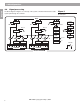
4.0 Installation
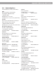
Figure 9
Connections to balanced amplifier.
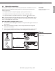
Figure 10
Connections to unbalanced
amplifier.
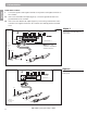
Note:
Pin 2 – hot
convention assembled
on XLR connector.
To
balanced
amplifier
To balanced amplifier
(Figure 9):
1. Connect the positive and negative terminals to the positive and negative terminals
on the controller.
2. Connect the ground terminal to the ground terminal on the controller.
To unbalanced amplifier
(Figure 10):
1. Connect the positive and negative terminals to the positive and negative terminals
on the controller.
4.2 Mechanical installation
When mounting the controller in a rack, place the heaviest units near the bottom of the
rack. A top-heavy rack can topple if bumped or shaken. For added safety, secure the rack
to a wall or ceiling.
Note: Air temperature around the controller should not exceed 120°F (50°C) when the
controller is on. If the controller is placed on a shelf with other heat-producing equipment,
ventilate the rack to prevent overheating.
Tip (+)
Ring (–)
Sleeve
1
/4" TRS
2 (+)
3 (–)
1
XLR
CUT NORMAL
CH B
PAGE
LEVEL
OPTI-VOICE
®
OUTPUT
LINE
OFF
CH A
OFF
CH B
PAGE PAGE
MODEL 32
CH A
OFF
CH B
PAGE
MODEL 8
CH A
OFF
CH B
PAG E
AUD
I
CAU
T
RISK OF
WITH SA
SLOW B
L
ATT
E
UN FUSI
B
REACTI
O
TYPE T
0
OPEN
MODEL 8/32 SYSTEM CONTROLLER
BOSE CORPORATION
FRAMINGHAM, MA 01701-9168 MADE IN U.S.A.
D.O.M.
SER.NO.
®
To
unbalanced
amplifier
CUT NORMAL
CH B
PAGE
LEVEL
OPTI-VOICE
®
OUTPUT
LINE
OFF
CH A
OFF
CH B
PAGE PAGE
MODEL 32
CH A
OFF
CH B
PAGE
MODEL 8
CH A
OFF
CH B
PAGE
AUDIO GND
CAUTION:
TO REDUCE THE
RISK OF FIRE, REPLACE ONLY
WITH SAME TYPE 0.25A-250V T
SLOW BLOW FUSE.
ATTENTION:
UTILISER
UN FUSIBLE DE RECHANGE Á
REACTION LENTE DE MÊME
TYPE T 0.25 - 250V.
OPEN GND
MODEL 8/32 SYSTEM CONTROLLER
BOSE CORPORATION
FRAMINGHAM, MA 01701-9168 MADE IN U.S.A.
D.O.M.
SER.NO.
®
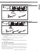
Tip (+)
Sleeve (–)
1
/
4
" phone
connector
3 (–)
2 (+)
1
XLR RCA
+
–
AM177675-2_04_V.pdf • May 7, 2002