FreeSpace® 4400 Business Music System OWNER’S GUIDE
Safety Information Please read this owner’s guide Please take the time to follow the instructions in this owner’s guide carefully. It will help you set up and operate your system properly and enjoy all of its advanced features. Please save this owner’s guide for future reference. WARNING: To reduce the risk of fire or electrical shock, do not expose the product to rain or moisture.
Important Safety Information Caution marks on the product 15. To prevent risk of fire or electric shock, avoid overloading wall outlets, extension cords, or integral convenience receptacles. 16. Do not let objects or liquids enter the product – as they may touch dangerous voltage points or short-out parts that could result in a fire or electric shock. 17. See product enclosure for safety related markings. 18. No naked flame sources, such as lighted candles, should be placed on the apparatus.
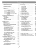
Contents 1.0 FreeSpace® 4400 Introduction . . . . . . . . . . . . . . . . . . . 1.1 The Bose® FreeSpace® 4400 Business Music System . . . . . . . . . . . . . . . . . . 1.2 FreeSpace 4400 system accessories . . . . . . . . . . 1.3 FreeSpace 4400 Installer™ software . . . . . . . . . . . . . . . . . . . . . . . . . . . . . . . 2.0 Designing with the FreeSpace® 4400 System . . . . . . . 2.1 Introduction . . . . . . . . . . . . . . . . . . . . . . . . . . . . . . 2.2 Basic design steps . . . . . . . . . . . . .
1.0 FreeSpace® 4400 Introduction 1.1 The Bose® FreeSpace® 4400 Business Music System • Serial Data Interface: RS-232 serial port for easy interfacing to your PC • Remote On/Off Input: Accepts a remote STANDBY switch The integrated 400-watt power amplifier features a patented power-sharing technology which dynamically allocates power to each output.
1.0 FreeSpace® 4400 Introduction 1.3 FreeSpace 4400 Installer™ software FreeSpace® 4400 Installer™ software is included with every FreeSpace 4400 system. The FreeSpace 4400 Installer software allows you to configure hardware devices such as the FreeSpace 4400 system. The FreeSpace 4400 Installer software is designed for use on a PC that is connected to the FreeSpace 4400 system through a serial data interface.
2.0 Designing with the FreeSpace® 4400 System 2.1 Introduction Guidelines for establishing Auto Volume zones This section describes the basic steps for designing a FreeSpace 4400 system and includes an example. It is assumed that a complete loudspeaker design and layout has already been created. Loudspeaker Background noise height is… is uniform >25 ft (7.6 m) 2.2 Basic design steps There are five basic steps in designing a FreeSpace 4400 system. 2.2.
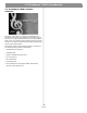
2.0 Designing with the FreeSpace® 4400 System The following are examples of correct and incorrect sensing microphone placements: Ceiling Flush Correct placement Incorrect placement Sensing microphone Sensing microphone Wall Surface Correct placement Incorrect placement Sensing microphone Sensing microphone Mic Installer’s Note: In applications where ceiling height is less than 12 ft (3.6 m), the microphone should be wall mounted.
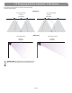
2.0 Designing with the FreeSpace® 4400 System When mounting sensing microphones, always maintain a distance of 6 ft (1.8 m) minimum between the microphone and the loudspeaker. Wall Surface Ceiling Flush Sensing microphone ≥6 6' ft (1.8 m) ≥6 ft (1.8 m) Mic ≥6 ft (1.8 m) Sensing microphone Ceiling Surface ≥6 ft (1.8 m) Mic ≥6 ft 6' (1.8 m) 6' Sensing microphone 6 of 66 ≥6 ft (1.
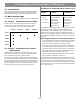
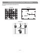
2.0 Designing with the FreeSpace® 4400 System 2.2.3 Step 3 – Determine volume control requirements 2.2.4 Step 4 – Determine the loudspeaker requirements Decide which areas will have volume controls. Create a control map, such as the following, showing the types of controls that will be used, and the areas in which they will be installed. Determine the loudspeaker coverage required for the design.
2.0 Designing with the FreeSpace® 4400 System 2.2.5 Step 5 – Determine the FreeSpace® 4400 requirements Once you have identified the areas that use Auto Volume and specifically equalized Bose loudspeakers, you can combine different areas based on the types of sources and controls they are using. Now we can take a look at how the maps we created can help us determine the quantity of FreeSpace 4400s we will need. Sources 1 2 3 Controls 4 ● AV1 AV2 VC1 Loudspeakers VC2 M32SE Total W 4400 Ch.
2.0 Designing with the FreeSpace® 4400 System 2.
2.
2.0 Designing with the FreeSpace® 4400 System Hotel lobby 22 ft (6.7 m) 40 ft (12.
3.0 FreeSpace® 4400 Hardware Description 3.1 Front panel 3 2 1 4 3.1.1 Controls 5 Green = Normal operation Red = Fault condition 1 STANDBY – The STANDBY button switches the unit Unlit = No signal between standby and active. The color of the LED above the switch indicates the status: 4 AUDIO SOURCES – These LEDs indicate the operating status of the four input sources: Amber = Unit is in standby Unlit = Unit is active Green = Good signal 3.1.
3.0 Freespace® 4400 Hardware Description 3.2 Rear panel 1 10 2 6 3 4 7 8 9 11 5 13 12 3.2.1 System controls 3.2.3 Amplifier outputs 1 SENSE MICROPHONES – Input connectors for sensing microphones used with the Auto Volume feature. 6 ZONE OUTPUTS 1/2/3/4 – Loudspeaker connections for four zones Installer’s Note: Please notice the polarity markings when wiring loudspeaker cables to the ZONE OUTPUT connectors. 2 RS-232 – Standard RS-232 communications port.
4.0 Hardware Installation 4.1 Introduction 4.3 Placement guidelines This section provides instructions for installing the FreeSpace 4400 system hardware on a tabletop or in a rack. • Place the FreeSpace 4400 system where it is protected from heat and allowed adequate ventilation. 4.2 Included accessories • Place the FreeSpace 4400 system away from direct heat sources, such as heating vents and radiators. ® The following accessories are shipped with the FreeSpace 4400 system.
4.0 Hardware Installation 4.5 Rack mounting the FreeSpace 4400 system The FreeSpace 4400 system requires three 1.75" (44 mm) rack space units with a 16" (406 mm) inside depth (including the rear supports). When mounting, use four screws with washers to prevent marring the front panel. Neoprene rubber washers are a good choice because they grip the screw head and prevent the screws from backing out from vibration or during transportation.
4.0 Hardware Installation 4.6 Installing accessories 4.6.2 Auto volume microphone inputs Connect each sensing microphone to the SENSE MICROPHONES jacks on the FreeSpace 4400 rear panel. Installer’s Note: Disconnect the FreeSpace 4400 system from the AC (mains) power before making any input/output connections. 4.6.1 Sensing microphones Required accessory: FreeSpace® 4400 System Auto Volume Mic Kit [PC042354 (U.S.), PC042355 (Euro)] Paint plug Wall plate-microphone assembly (2) Wire nuts 4.6.
4.0 Hardware Installation Assembly: User interface schematic Page user interface: E 12345678 +5VD +5VD .33µF C7 D1 LED A D6 LED D B R6 562 +5VD R1 562 MU AU TE / TO VO L S6 S1 Zone 1 +5VD +5VD User interface schematic AVM (Auto Volume/Mute)user interface*: Zone 2 D5 LED D2 LED 12345678 R5 562 +5VD R2 562 +5VD .
4.0 Hardware Installation 4.6.4 User interface connections User interface wiring: Installer’s Note: Use only standard ethernet (Cat 5) cable to connect the user interface to the FreeSpace 4400 system. DO NOT use crossover (XOV) cables. Connect the user interface from each zone to the appropriate WALL PLATE CONNECTION jack. Installer’s Note: Only use standard ethernet (Cat 5) cable to connect the user interface to the FreeSpace 4400 system. DO NOT use crossover (XOV) cables.
4.0 Hardware Installation 4.7 System wiring 4.7.2 Remote standby switch If you are installing a remote standby switch, connect it to the REMOTE ON/OFF input. Installer’s Note: Disconnect the FreeSpace 4400 system from the AC (mains) power before making any input/output connections. Remote Standby Switch 4.7.1 Serial data communications Connect your PC to the FreeSpace 4400 system using a straightwired serial data cable (DB9 male to DB9 female).
4.0 Hardware Installation 4.7.3 LINE 1/LINE 2 source input 4.7.4 AUX MIC/LINE 3 source input Audio sources can be connected to the LINE 1 and LINE 2 inputs using one of the following cable types. A microphone or an audio source can be connected to the MIC/ LINE 3 input using one of the following cable types.
4.0 Hardware Installation 4.7.5 PAGE/MIC/LINE 4 source input 4.7.6 DIRECT IN/CONTROL source input A microphone or an audio source can be connected to the PAGE/ MIC/LINE 4 input using one of the following cable types. A microphone or an audio source can be connected to the DIRECT IN input using one of the following cable types. The control (PTT) input requires a normally open switch.
4.0 Hardware Installation 4.7.7 Amplifier ZONE OUTPUT outputs 4.7.8 Output voltage setting (70/100V) Loudspeaker systems in up to four zones can be connected to the ZONE OUTPUT amplifier outputs. Check the OUTPUT VOLTAGE switch setting and change if needed. Installer’s Note: Please notice the polarity markings on the ZONE OUTPUT 1-4 connectors. Wire each connection as shown, using the 2-terminal output connector from the accessory kit.
4.0 Hardware Installation 4.7.9 ZONE 4 LINE OUT output 4.8 AC power connections The ZONE 4 LINE OUT jack provides a line-level output that duplicates the program material on LINE 4. This may be used to feed another Bose® amplifier installed for a large zone. The 12V control output is used to connect to Bose amplifier sequence inputs. The rear connection panel of the chassis provides an input voltage switch for 100V, 120V, 220V, 230V, or 240V use.
5.0 Using FreeSpace® 4400 Installer™ Software 5.1 Installing the software 2. Insert the FreeSpace® 4400 Installer™ software CD into the CD tray of your laptop PC. If the install program does not start automatically, open “My computer” from the desktop, double-click on the CD-ROM drive icon, and double-click on the “Setup.exe” icon. Set the FreeSpace 4400 rear panel POWER switch to ON. Verify that the STANDBY indicator is lit on the FreeSpace 4400 front panel.
5.0 Using FreeSpace® 4400 Installer™ Software 3. Launch the FreeSpace 4400 Installer™ software. Programmer’s Note: If you encounter the “Choose COM port” dialog box, immediately follow the displayed recommendations for correcting the problem. DO NOT click the Cancel button until after trying each of the given recommendations. The FreeSpace 4400 Installer software splash screen will appear on your screen.
5.0 Using FreeSpace® 4400 Installer™ Software 5.2.1 No hardware detected If after launching the FreeSpace 4400 Installer™ software a hardware device is not found, the status window reports a failure to detect connected hardware: In this case, clicking the Close button results in a blank hardware setup window. • Click Upgrade to upload the latest version of microcontroller code to the device. When the "Upload Complete" window appears, click Close.
5.0 Using FreeSpace® 4400 Installer™ Software 5.3 The FreeSpace 4400 Installer™ software user interface The following describes the software user interface.
5.0 Using FreeSpace® 4400 Installer™ Software Tool box Open File – Displays the file open dialog. System overview pane – After connecting your PC to a system, this pane will list the hardware device. After you select the device to establish a connection, the name of the hardware device is highlighted. Save File – Saves the design file and the current settings of the connected hardware device to your PC’s hard drive.
5.0 Using FreeSpace® 4400 Installer™ Software 5.4 Set Up Hardware mode Using the Set Up Hardware mode, you can create new system configurations. The following example displays the software front panel for the FreeSpace® 4400 system. The hardware setup window consists of three panes: System overview pane – This pane displays the selected hardware device that you are currently configuring. For more information on the system overview pane, see “The FreeSpace 4400 Installer™ software user interface” on page 27.
5.0 Using FreeSpace® 4400 Installer™ Software 5.5 Set Up Schedule mode The Set Up Schedule mode allows you to automate a system by creating up to 64 events. To select the Set Up Schedule mode, click the Schedule button under Set Up System. The features and controls of the Set Up Schedule window are as follows: Event list selection tabs – These tabs determine which list of events is displayed. Click the top tab to display the system event list.
5.0 Using FreeSpace® 4400 Installer™ Software 5.5.1 Setting the clock The date and time of the hardware clock is initially set in Eastern Standard Time. After your PC is connected to the hardware, check the clock and set it as necessary for the time zone and region of your installation. Adds a system Auto On/Off event This event applies only to the whole system. You can select individual on or off times for the day(s) you choose. Or, you can select on and off times in a single statement.
5.0 Using FreeSpace® 4400 Installer™ Software 5.5.3 Viewing and changing event settings Adds a zone Source Change event This event allows you to change the source at a specified time on selected days of the week. To view any event and change the settings, first click the system or one of the zone tabs. Then select an event in the list to display the event settings in the control pane. Now, you can edit the settings just as when an event is added. 5.5.
5.0 Using FreeSpace® 4400 Installer™ Software 5.6 Service Hardware mode Service Hardware button The Service Hardware mode provides a list of any system errors that have occurred. To view the Error Log, click the Service Hardware button. If you are already connected to hardware, the Error Log is retrieved from the hardware and displayed in the window. If not yet connected, select the hardware in the System Overview pane and after establishing the connection, click and then click (Detect Hardware) .
6.0 FreeSpace® 4400 System Setup 6.1 Introduction Rear POWER switch Front SYSTEM STATUS indicator Green = Operating Red = Fault This section provides instructions on setting up an installed FreeSpace 4400 system. To set up a FreeSpace 4400 system you need a PC running the FreeSpace® 4400 Installer™ software. 6.
6.0 FreeSpace® 4400 System Setup 6.3 System setup procedure 6.3.1 Output gain The first time you turn on a FreeSpace 4400 system it loads its factory (default) configuration settings. These settings were stored in the FreeSpace 4400 when it was manufactured. Once your PC is fully connected to the FreeSpace 4400 system, you can use the FreeSpace 4400 Installer™ software to make changes to the factory configuration settings.
6.0 FreeSpace® 4400 System Setup 2. Set the minimum output gain. This sets the desired minimum volume within a zone. Play a source that will be used in the zone and adjust the volume slider to the desired minimum level. Raise the minimum gain stop up to the volume slider level. 3. Set the initial output gain. When the FreeSpace 4400 system is switched from standby to operating mode, it loads its configuration (initial settings).
6.0 FreeSpace® 4400 System Setup 6.3.3 Input gain Programmer’s Note: If you are using the FreeSpace 4400 system to drive loudspeakers that are not Bose® products, choose the No EQ setting or one of the four high-pass filter settings at the end of the list. The Input Gain controls allow you to adjust functions related to the input source signal.
6.0 FreeSpace® 4400 System Setup Input gain setup sequence Input gain meter – The input gain meter indicates the average input signal level of the hardware. The meter is divided into three color segments: 1. Set Opti-source® Control to Off. This allows you make the initial gain setting. 2. Select the source Type and determine if Mic Power +12V is needed. Set Mic Power to On if required. Leave it in the Off setting if you are using line inputs.
6.0 FreeSpace® 4400 System Setup 6.3.4 Source assign When the source appears in the ZONE Sources list, it is assigned to the current zone. Once a source is assigned to a zone, that source is no longer available in the System Sources list and appears grayed out. In the Source Assign control, you can choose which system sources will be available in each zone. The Source Assign control panel lists all system sources on the left and zone sources on the right.
6.0 FreeSpace® 4400 System Setup To set up paging in a zone 6.3.6 Page setup In order to use paging in a zone, first you must assign the PAGE source to the zone. Then select the appropriate settings in the Page Setup (page 40) control pane. The Page Setup control panel is used to set up the PAGE/MIC/ LINE 4 input for paging. The page setup is available when “Mic/ Page” or “Line/Page” is selected for “Type” in the Input Gain control panel.
6.0 FreeSpace® 4400 System Setup Page setup with Opti-voice® control off Setting up Multi-zone paging 1. Set Opti-voice to Off in the Page Setup control panel. This enables the Ducking Depth and Release Time controls. 1. Assign the PAGE source to all zones that will be paged. See “To set up paging in a zone” on page 40. 2. Set the Ducking Depth to the amount in dB that the music will be reduced to once a page is triggered. 3. Set the Release Time to the length of time (secs.
6.0 FreeSpace® 4400 System Setup Paging operation 6.3.7 Zone EQ When a page signal is triggered, the music signal is ramped down according to the ducking time. The ducking time is preset at 20 ms for Auto detection and 0 ms for PTT triggering. The music level is reduced by the ducking depth which can be adjusted using the ducking depth control. Ducking depth is adjustable from 0 to –40 dB.
6.0 FreeSpace® 4400 System Setup 6.3.8 Dynamic EQ • DO NOT USE AUTOTRANSFORMERS: DO NOT use an autotransformer on the loudspeaker line to adjust the loudspeaker volume. Dynamic EQ will not operate properly with this added component. The Dynamic EQ control panel provides an on/off control to enable/disable Dynamic Equalization in the current zone.
6.0 FreeSpace® 4400 System Setup IMPORTANT: Before you calibrate Auto Volume Auto Volume setup procedure Programmer’s Note: While the Auto Volume calibration is running, • Make sure that the system hardware installation is complete and that all components (sense microphones, loudspeakers, and AVM (Auto Volume) user interfaces) are properly connected. Remember that loudspeakers must be directly wired to the ZONE OUTPUT connectors on the FreeSpace 4400 rear panel.
6.0 FreeSpace® 4400 System Setup 5. 6. Click Continue. Your Auto Volume Tracking settings are confirmed. If the tracking settings are not correct, click the Cancel button, change the settings, and start the setup process again. 7. Click Continue. All sources assigned to the zone are listed in the window. You are asked to confirm that a source is connected and operating.
6.0 FreeSpace® 4400 System Setup 8. Click Continue to begin the source calibration process. 9. The source calibration process takes about three minutes per source. For each source, the input gain is measured and optimized, and the source level is activated. When this is done, the software displays the following confirmation. 46 of 66 Click Continue to begin the Zone Microphone Calibration. This calibration is performed using a test signal at the maximum zone volume and takes about 5 minutes.
6.0 FreeSpace® 4400 System Setup Programmer’s Note: If this process fails, a dialog similar to the following will appear. Check the sensing microphone installation and make sure all sources are operating. Following a successful microphone calibration, the software automatically flashes the hardware to save the configuration. 10. At the end of a successful Auto Volume calibration, the software displays a list of controls that are disabled when Auto Volume is on. Click Finish to exit Auto Volume Setup.
6.0 FreeSpace® 4400 System Setup When to repeat the Auto Volume calibration You will need to repeat the Auto Volume process if: Band pass filter ZONE source input • You reset a calibrated zone. • You physically replaced source hardware. • You moved a sensing microphone. • You changed a loudspeaker tap. Auto Volume Algorithm • The source hardware has an output control and you changed its setting after you calibrated Auto Volume.
7.0 User Interface Operation 7.1 Enabling keypad operation off controls for use with two zones. FreeSpace® AVM 2-Zone User Interface User interface keys for assigned sources are enabled only after flashing the hardware. Keys for any unassigned sources are automatically disabled after flashing the hardware. 7.
7.
7.0 User Interface Operation 7.4 Page user interface operation Page User Interface Example: • The PAGE source is assigned to ZONE OUTPUT 1 and ZONE OUTPUT 4. The Page user interface provides keys to select single paging zones, all paging zones and initiate a page. Paging zones are not the same as output zones. After assigning the PAGE source to the output zones and choosing the appropriate settings in the Page Setup control pane, flashing the hardware maps the paging zone buttons accordingly.
8.0 FreeSpace® 4400 System Troubleshooting 8.1 Introduction This section provides troubleshooting guidelines to use for solving any problems you may encounter while installing and servicing FreeSpace 4400 systems. To determine the severity of the error, cycle the FreeSpace 4400 system power off and back on again. If the SYSTEM STATUS indicator is now off, the FreeSpace 4400 system has logged an error, but is still operational.
8.0 FreeSpace® 4400 System Troubleshooting 8.2.3 Amplifier fault The AMP OUTPUT LEDs work in pairs (1 and 2, 3 and 4) and indicate the operating status of the four amplifier output channels.
8.0 FreeSpace® 4400 System Troubleshooting 8.2.4 Input clipping 8.2.6 No STANDBY and SYSTEM indicators If clipping is occurring at the input of an amplifier channel, the source LED will blink red. OUTPUTS 1 2 3 4 STANDY & SYSTEM LEDs are off - AC power is on SYSTEM STATUS STANDBY 1 2 3 4 INPUTS Is FreeSpace 4400 unit plugged into an AC source? DIRECT INPUT If this fault occurs: No Plug the FreeSpace 4400 system into an AC receptacle.
8.0 FreeSpace® 4400 System Troubleshooting 8.3 FreeSpace® 4400 system Error Log The FreeSpace 4400 system Error Log is displayed when the FreeSpace 4400 Installer™ software is in the Service Hardware mode. 8.3.1 Contents of the Error Log The Error Log displays FreeSpace 4400 system hardware version numbers and records all alarms and their causes as shown in the following example.
8.0 FreeSpace® 4400 System Troubleshooting 8.3.4 Amplifier alarms Amplifier alarms – using output voltage and current Each amplifier section monitors its own operation and performance. If a fault condition occurs, it is reported in the Amplifier Alarm section of the Error Log. Upper amplifier alarms affect channels 1 and 2, and Lower amplifier alarms affect channels 3 and 4. Reviewing the output voltage and current can help to diagnose a problem.
8.0 FreeSpace® 4400 System Troubleshooting A number of fault conditions can be displayed in the Input Status section: DC Sense Fault: A power supply fuse, output FET, amplifier module, or some combination of the above has blown. The unit should be replaced. Generally, this fault results in a one-time 3-second dropout. If, when the amplifier tries to restart after 3 seconds, the excess HF is still present, the amp (and loudspeaker relay) will remain off for another 3 seconds and the loop repeats.
8.0 FreeSpace® 4400 System Troubleshooting 8.4 Common problems 8.4.2 No audio in zone 8.4.1 Communications port error If the system is powered on and operational, but there is no sound, check the following: When you receive the communications port error dialog, the FreeSpace® 4400 Installer™ software was not able to locate a FreeSpace 4400 system on the COM 1 port.
8.0 FreeSpace® 4400 System Troubleshooting 8.4.3 User interface keypads do not operate correctly 8.4.4 Bad sound in a zone • Check wiring of RJ-45 connectors. Bad sound • Check for breaks/shorts in cable. • Using the FreeSpace 4400 Installer™ software, check the Error Log for a peripheral controller error. User interface keypads exhibit strange behavior Is the sound unnatural? Yes Verify that the correct Speaker EQ is selected in the FreeSpace 4400 Installer™ software for that zone.
8.0 FreeSpace® 4400 System Troubleshooting 8.4.5 Auto Volume does not calibrate 8.5.2 Reporting software bugs and issues Auto Volume calibration may fail if the process cannot obtain an adequate source level. This may be due to: Please email any problems, issues, or software bugs to your local Bose representative.
8.0 FreeSpace® 4400 System Troubleshooting To find the temporary file directory… For Windows 2000, or Windows XP: 1. Right-click My Computer on the Windows desktop. 2. Select the Properties menu item. 3. Click the Advanced tab. 4. Click the Environment Variables... button. 5. Scroll down to the value of variable TEMP under “User variables”. If, and only if, it is not found there, look under System variables instead. For Windows NT: 1. Right-click My Computer on the Windows desktop. 2.
9.0 Restoring FreeSpace® 4400 Microcontroller Code 6. Press and hold the Ctrl and Alt keys on your PC keyboard IMPORTANT! and click the (Flash Configuration) button. The Upload Microcontroller Code dialog appears: DO NOT use this procedure to upgrade the firmware in your FreeSpace® 4400 system to any version other than the version running at the time that the design file was created.
9.0 Restoring FreeSpace® 4400 Microcontroller Code The firmware upgrade runs automatically and will notify you when it is complete. Once the upgrade is completed, select the Service Hardware mode and verify that the microcontroller version number is correct. For example: ------------------------------------------------Microcontroller: v3.0.0.18 DSP: v2.0.1.0 Peripheral: v1.0.0.10 Lower Amplifier: v1.1.8.5 Upper Amplifier: v1.1.8.
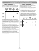
10.0 Technical Specifications 10.1 Power amplifier Direct input Total shared power available for all channels: 400W Maximum power per channel: 400W Type: Balanced Euroblock connectors Sensitivity: 0 dBV Impedance: 10K ohms Input Clip Level: +6 dBV Output configurations Sensing microphone inputs Power output 70.
65 of 66 0x840x000x030x010x000 x510x000x010x000xda 0x840x000x030x010x000 x510x010x010x000xdb 0x840x000x030x010x000 x510x020x010x000xdc 0x840x000x030x010x000 x510x030x010x000xdd 0x840x000x030x010x040 x910x010x050x010x24 0x840x000x030x010x040 x910x010x010x010x20 0x840x000x030x010x040 x910x000x010x010x1f 0x800x000x010x010x000 x340x010xb7 0x800x000x010x010x000 x340x000xb6 0x840x000x030x010x010 x1D0x010x010x000xA8 0x840x000x030x000x000 x510x000x010x000xd9 0x840x000x030x000x000 x510x010x010x000xda 0x840x000x030
How you can obtain Limited Warranty service: Bose® Product Sales Conditions You can ship the system to either a Bose Service Agency or to Bose directly with a proof of purchase from an authorized dealer. Limited Warranty Policy and Conditions of Sale Please: A. Properly and carefully pack the product for shipping. If you need a carton for shipping, contact Bose for a new carton. Bose Corporation The Mountain Framingham, MA 01701 B. Label and ship the product to the appropriate Bose location. C.
66 ©2007 Bose Corporation, The Mountain, Framingham, MA 01701-9168 USA AM301433 Rev.