ControlSpace™ CC-64 Control Center Safety Instructions & Install Guide
Important Safety Instructions For the intended audience This guide has been written for professional installers of sound systems. 1. Read these instructions – for all components before using this product. 2. Keep these instructions – for future reference. 3. Heed all warnings – on the product and in the installer’s guide. 4. Follow all instructions. 5. Do not use this apparatus near water or moisture. 6. Clean only with a dry cloth – and as directed by Bose. 7. Do not block any ventilation openings.
Important Safety Instructions • Reorient or relocate the receiving antenna. • Increase the separation between the equipment and receiver. • Connect the equipment to an outlet on a different circuit than the one to which the receiver is connected. • Consult the dealer or an experienced radio/TV technician for help. Note: Unauthorized modification of the equipment could void the user’s authority to operate this equipment. This product complies with the Canadian ICES-003 Class B specifications.
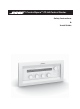
Introduction Introduction The Bose® ControlSpace™ CC-64 control center is an elegant, programmable, networked controller that provides users with a simple and logical interface to their ControlSpace system. Because the controller is completely programmable, you can customize the ControlSpace system, making only certain controls available, and simplifying user interaction with the system.
Introduction Features • 2-line by 40-character backlit LCD • • • • Sixteen Gain/Selector controls (four banks of four) - Four rotary encoders for changing the gain level or selecting Introduction scenes/sources - Each encoder includes a 15-segment LED array for indicating the control’s current level or state - The encoders feature push buttons for muting gain controls or making selections - Ten character descriptions of the gain controls appear on the LCD above the encoder Four bank switch buttons with
Front Panel Front panel Introduction Functions 1. LCD 2. Preset/Scene selector Rotate to view presets. Push to select. Push and hold for 5 seconds to enter Custom mode. 3. Network link indicator 4. Network receive indicator 5. Network transmit indicator 6. Bank select buttons (4) Press to select one of four bank controls 7. Bank select indicators (4) Indicates the currently selected bank 8. Bank select label area 1.25" (31.75 mm) x .35" (9 mm) area for custom labels.
Installation Quick start What you will need: The following items are needed for most installations: - 5-gang electrical wall box Installation - UTP Cat-5 cable terminated with RJ45 plugs (standard Ethernet wiring) - Ethernet hub - Power supply (not included with the CC-64) WARNING: The product must be connected to a limited-power (<240VA) power supply. Step 1: Wiring Run a Cat-5 cable from a hub or router to the CC-64 location.
Connections Installing the wall box We recommend steel, 5-gang, masonry boxes for wall-mounting. Install the wall box so that it is flush or just below the surface of the finished wall. Select a place that is convenient for users. We suggest mounting the unit at eye level for optimal LCD viewing angle. CAUTION: Do not install the control center in a box that has AC power (mains).
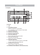
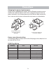
Connections Changing the power input jumpers Power can be supplied directly to the 2-terminal Phoenix connector or over the Ethernet cable. By default, the CC-64 is configured for power from the power connector. If you choose power over the Ethernet cable, remove the four screws on the rear cover and move the two jumpers as shown below.
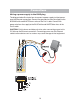
Connections Wiring a power supply to the RJ45 plug The diagram below illustrates how to connect a power supply to inject power over the Ethernet connection. Connect the ground wire from the supply to the BROWN/white and WHITE/brown wires of the Cat-5 cable. Connect the power wire from the supply to Installation the BLUE/white and WHITE/blue wires of the Cat-5 cable. CAUTION: Cut the brown and blue pair wires when connecting power to the CC-64 over the Ethernet connection.
Troubleshooting No power • Ensure that power supply is wired correctly and plugged in. • Verify that the supply is DC and provides at least 300mA at 15V. • If supplying power over the Ethernet, check that jumpers behind the back panel are in the correct position. Screen is blank • Press a button to see if backlight comes on. (The backlight turns off No response when • Check that the Selector or Gain/Selector parameters have been after a period of inactivity.
Reference Mounting cutout To mount the CC-64 in a blank rack panel, podium or other location where an electrical box is not practical, use the dimensions below as a guide for creating a cutout.
Warranty Bose® Product Sales Conditions Limited Warranty Policy and Conditions of Sale Bose Corporation The Mountain, Framingham, MA 01701 What is covered: All parts defective in material and workmanship.
Warranty OTHER CONDITIONS: FOR YOUR BENEFIT, WE RECOMMEND THAT YOU RECORD YOUR SERIAL NUMBER(S), FOUND ON THE PRODUCT(S), AND OTHER PURCHASE INFORMATION, AND KEEP IT WITH YOUR PERSONAL RECORDS ALONG WITH PROOF OF PURCHASE. IF NECESSARY, THIS INFORMATION WILL ALLOW US TO BETTER SERVE YOUR NEEDS. THIS LIMITED WARRANTY GIVES YOU SPECIFIC RIGHTS SUBJECT TO SPECIFIED CONDITIONS. YOU MAY ALSO HAVE OTHER LEGAL RIGHTS WHICH APPLY TO THE PRODUCT YOU HAVE ACQUIRED.
Warranty 15
©2005 Bose Corporation, The Mountain, Framingham, MA 01701-9168 USA 285041 AM Rev.