ControlSpace® Engineered Sound Processor Safety Instructions & Install Guide
Important Safety Instructions Caution marks on the product may expose you to dangerous voltages or other hazards. Please call Bose to be referred to an authorized service center near you. These CAUTION marks are located on the back of the product. The lightning flash with arrowhead symbol, within an equilateral triangle, is intended to alert the user to the presence of uninsulated dangerous voltage within the system enclosure that may be of sufficient magnitude to constitute a risk of electric shock. 15.
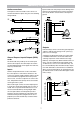
Important Safety Instructions Rack mounting considerations General precautions This audio signal processor requires two 1.75" (4.4 cm) rack space units with 12.8" (32.5 cm) inside depth. When mounting, use four screws with washers to prevent marring the front panel. Neoprene rubber washers are a good choice because they grip the screw heads and prevent the screws from backing out due to vibration or during transportation.
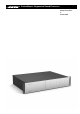
Introduction Introduction Quick start The Bose® ControlSpace® Engineered Sound Processor is a flexible, expandable and high-quality digital audio signal processor. The ESP-88 (base model) includes eight inputs (microphone or line-level selectable) and eight line level outputs. Four available audio slots allow up to 64 channels of audio. • Install the ControlSpace Designer software included with the ESP (always check www.pro. bose.com for latest version.
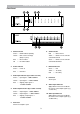
Front Panel Indicators and Features Front Panel 1. Status indicator 6. Serial indicator Green = Netlist loaded, operating Red Yellow = DSP resource shortage (delay or cycles) Red = Error in netlist Off = No netlist loaded = RS232: Rx/Tx Yellow = RS485: CC-16 controller command received Green = RS485: CC-16 controller command transmitted 7. Ethernet indicator 2. Power indicator Green = Power on Green Red Yellow = Tx activity = Fatal error Red = Link = Rx activity 3.
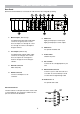
Rear Panel Controls and Connections Rear Panel (ESP-88 shown ESP-00 does not include I/O cards and must be configured separately.) 1. Mic/line inputs (ESP-88 only) 5. GPIO card Four balanced mic/line inputs (audio input connectors are green) in slots 1 and 3. These are inputs S1-1 through S1-4, and S3-1 through S3-4 in the ControlSpace™ Designer software. Eight general purpose control inputs Eight general purpose control outputs 6. GPIO slot 2 For optional 2nd GPIO card 2.
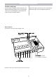
Modularity and Expansion Flexible architecture Remove the eight screws from the cover of the ESP and slide off the top to access the expansion card slots. The ESP employs a flexible, modular architecture. The flexible architecture provides two levels of DSP performance: up to 32 general purpose control inputs and outputs, and up to 64 audio channels.
Modularity and Expansion Expansion cards Maximum expansion card configuration Three types of optional cards are available: DSP expansion; GPIO; and Audio. The ESP-00 has eight available audio expansion slots and two available GPIO slots. DSP expansion card PC041769 Daughter card for main DSP card. Increases performance by 300%. One card can be added to an ESP. GPIO card PC041768 Fits in the available GPIO slot. Eight control inputs and eight control outputs. One GPIO card can be added to an ESP.
Modularity and Expansion Audio connections Inputs include a 5k ohm pull-up resistor allowing SPST switches to be wired from input to ground. Potentiometers can be wired in series from the control input to ground. A microphone or line level audio source can be connected to the Mic/Line inputs using one of the following wiring methods. Outputs LEDs and relays can be connected to general purpose outputs to indicate state changes in the system (e.g. preset or scene changes). A maximum of 10mA (sink; 0.
Troubleshooting No Power • Turn power on, plug in power cord. Power is on but no sound • Verify that there is an input signal from the source. The audio input indicator should be green (or yellow). • Verify that there is an output signal. The audio output signal indicator should be green (or yellow). • If there is an input signal (indicator green) and no output signal (indicators off), the ESP may be muted, output levels may be down, or the unit may be completely unprogrammed.
Technical Specifications Audio channels Signal processing Type 32-bit floating-point digital signal processor(s) Analog 32 max (all slots full) Clock speed 200MHz Digital (AES3) 64 (all slots full) Maximum calculation 1600 MIPS/1200MFLOPS (6400MIPS/4800MFLOPS with DSP option card) Mechanical Delay memory 16MByte/72s(Maximum) (64MByte/288s(Maximum) with DSP option card) Audio latency 610us (analog in to analog out) (860us with DSP option card) Sampling rate 48kHz 10Base-T (RJ-45) RS-23
Technical Specifications Dimensions 10
Warranty Bose® Product Sales Conditions Other Rights: Limited Warranty Policy and Conditions of Sale Bose Corporation EXCLUSIVE REMEDY: THIS LIMITED WARRANTY IS FULLY TRANSFERABLE The Mountain, Framingham, MA 01701 PROVIDED THAT THE CURRENT OWNER FURNISHES THE What is covered: ORIGINAL PROOF OF PURCHASE FROM AN AUTHORIZED All parts defective in material and workmanship. This limited BOSE DEALER.
2008 Bose Corporation, The Mountain, Framingham, MA 01701-9168 USA AM316788 Rev 00