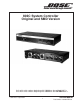
® ® 802C System Controller Original and SMD Version Units with serial numbers beginning with 100000 are the original 802C's. Units with serial numbers beginning with 200000 are the new SMD 802C's.
Contents Safety Information ............................................................................................................................ 3 Electrostatic Discharge Sensitive (ESDS) Device Handling ........................................................ 4 Specifications ................................................................................................................................... 5 Technical Description ......................................................................
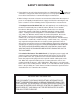
SAFETY INFORMATION 1. Parts that have special safety characteristics are identified by the symbol on schematics or by special notes on the parts list. Use only replacement parts that have critical characteristics recommended by the manufacturer. 2. Make leakage current or resistance measurements to determine that exposed parts are acceptably insulated from the supply circuit before returning the unit to the customer. Use the following checks to perform these measurements: A.
ELECTROSTATIC DISCHARGE SENSITIVE (ESDS) DEVICE HANDLING This unit contains ESDS devices. We recommend the following precautions when repairing, replacing or transporting ESDS devices: • Perform work at an electrically grounded work station. • Wear wrist straps that connect to the station or heel straps that connect to conductive floor mats. • Avoid touching the leads or contacts of ESDS devices or PC boards even if properly grounded. Handle boards by the edges only.
SPECIFICATIONS Input Connections: (per channel) One (1) balanced female XLR connector One (1) unbalanced 1/4" phone jack Output Connections: (per channel) Two (2) 1/4" phone jacks per channel (outputs used depend upon mode selected) Input Impedance: Balanced input, 4kΩ Unbalanced input, 42kΩ Electronic Crossover Frequency: 180Hz (bi-amplified mode only) Maximum Output Level: 4 Volts (+12dB into 600Ω, 50Hz-16kHz) Total Harmonic Distortion: Less than .02% at 1 Volt (0dB) Less than .
TECHNICAL DESCRIPTION The 802®C System Controller is a sophisticated signal processing device which combines the functions of three equalizers, an automatic switching circuit, and an electronic crossover. The 802C system controller automatically selects the proper crossover function and equalization curve for a given system application through use of a switching network operating in conjunction with the unit's output jacks.
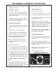
DISASSEMBLY/ASSEMBLY PROCEDURES Note: Refer to the Figures (2 and 3) for the following procedures. 4.2 Perform procedure 2. 5. Main PCB Removal 1. Top Cover Removal 5.1 Perform procedure 1. 1.1 Remove the four screws (two located at the rear of the unit and one located on each side of the unit) that secure the top cover to the chassis. 5.2 Remove the 6 knurled nuts securing the input and output jacks to the chassis. 5.3 Remove the 5 screws that secure the main PCB to the chassis. 1.
Figure 2. Original 802C PCB Exploded View Figure 3.
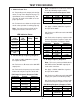
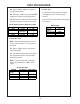
TEST PROCEDURES Note: Set both the Lo and Hi cut switches IN for the following response table. 1. Mode Indicator Test Lo and Hi Cut Switch Response Table 1.1 Depending on the output jack configuration (see top cover diagram on page 17), equalization curves and output vary. You must test all modes of the 802C to assure proper operation. Frequency 55Hz 750Hz 15kHz 1.2 Perform the test below to verify that the mode select operation is working properly. Tolerance ± 1.8dB ± 2.0dB 3.
TEST PROCEDURES 4.4 Apply a 100Hz, 500mVrms signal to the input of the 802C. 6. Noise Test 4.5 Reference a dB meter to the 302 AMP output jacks (while in the Bi-Amp mode). 6.1 All noise measurements are ANSI A-weighted true rms, with the inputs shorted. 4.6 Refer to the frequency response table below and verify the response of the unit. 6.2 Refer to the table below for the proper noise levels. 302 Bi-Amp Frequency Response Table Frequency 55Hz 100Hz Output +3.7dB 0dB (reference) -8.3dB -25.
PART LIST NOTES 1. This part is not normally available from Customer Service. Approval from the Field Service Manager is required before ordering. 2. The individual parts located on the PCB are listed in the Electrical Part List. 3. This part is critical for safety purposes. Failure to use a substitute replacement with the same safety characteristics as the recommended replacement part might create shock, fire and or other hazards. 4. RC-4156 is to be used ONLY as a replacement for U5 and U6.
MAIN PART LIST Item Number 1 2 3 4 5 6 7 8 9 10 11 12 13 14 15 16 17 Reference Designator J1, 3 J2, 4-8 J9 J9 J10 J10 P1, 2 T1 (See Figure 4) Description COVER CHASSIS FEET SCREW, SHEET METAL, 4-40 x .25L CONNECTOR, XLR NUT, KNURLED STRAIN RELIEF BUSHING LINE CORD, 100/120V LINE CORD, 220V LED BRACKET, LED SMD PCB ASSEMBLY SWITCH, KNOB SWITCH, DUAL SCREW, MACHINE, 4-40 x .
Figure 4.
ELECTRICAL PART LIST Resistors Reference Designator Description R1, 2 2.7kΩ, 1/4 Watt, 5% R3, 4 3.3kΩ, 1/4 Watt, 5% R5-7, 11, 15, 118, 218 160kΩ, 1/4 Watt, 5% R8, 9, 12, 13, 16, 17, 101, 210, 104, 204 R10, 14, 18 R102, 103, 105, 122, 124, 202, 203, 205, 222, 224 R106, 206 330kΩ, 1/4 Watt, 5% R107, 207 48.7kΩ, 1/4 Watt, 1% R108, 208 20kΩ, 1/4 Watt, 5% R109, 126, 130, 131, 209, 226, 230, 231 R110, 210 23.
ELECTRICAL PART LIST Resistors (continued) Reference Designator Description Part Number 1177041215632 1199762214121 1199762212372 1199762213092 1177041212235 Note Note 2.7kΩ, CHIP, 5% 3.3kΩ, CHIP, 5% 160kΩ, CHIP, 5% 330kΩ, CHIP, 5% 2.00kΩ, CHIP, 1% Part Number 124895-2725 124895-3325 124895-1645 124895-3345 124894-2001 1,91kΩ, CHIP, 1% 48.7kΩ, CHIP, 1% 20kΩ, CHIP, 5% 23.7kΩ, CHIP, 1% 124894-1911 124894-4872 124895-2035 124894-2372 2.74kΩ, CHIP, 1% 13.3kΩ, CHIP, 1% 1kΩ, CHIP, 5% 10kΩ, CHIP, 5% 8.
ELECTRICAL PART LIST Capacitors Reference Designator Description C1 .0047uF, 220V .0047uF, 1.4KV, 100/120V Part Number 120993 103447 C2, 3 C4 C5, 6 C7-10 C11-19, 22 C101, 117, 125, 201, 217, 225 C102, 202 C103-105, 203-205 C106, 206 C107, 108, 121, 122, 207, 208, 221, 222 C109, 209 C110, 126, 127, 210, 226, 227 C111, 211 C112, 113, 124, 212, 213, 224 C114, 214 C115, 116, 123, 215, 216, 223 C118, 119, 218, 219 C120, 220 .015uF, FILM .01uF, CERAMIC DISC 470uF, ELECTROLYTIC 1uF, ELECTROLYTIC .
ELECTRICAL PART LIST Diodes Reference Designator D1-5 D1, 101, 104, 201-204 Z1 Description ZENER, 18V, 1W, IN4746A 1N4148, DIODE BRIDGE RECTIFIER Part Number 116995-4746A 121501 112027 Note Part Number 117921 119168 Note Part Number 120535/192166 121116-1 121117-1 121854 192166 119837 Note 3 Transistors Reference Designator Q1, 4, 5 Q2, 3, 6 Description TRANSISTOR NPN TRANSISTOR PNP Integrated Circuits Reference Designator U1, 8, 9 U2 U3 U4 U5, 6 U7, 10 Description QUAD OP AMP, LS-404 VOLT REG,
VOLTAGE CONVERSION INSTRUCTIONS Voltage Conversions are to be performed on Military units. However it is possible to convert a 110 Volt unit (by replacing the transformer) and a 220 Volt European unit. 1. 220 Volt to 110 Volt Conversion 2. 110 Volt to 220 Volt Conversion Note: Conversions must be performed with the line cord disconnected from any power source. Refer to Figure 3 below for the following procedures. The jumpers listed in parentheses refer to the SMD units. 2.
Figure 6.
SPECIFICATIONS AND FEATURES SUBJECT TO CHANGE WITHOUT NOTICE ® ® Bose Corporation The Mountain Framingham Massachusetts USA 01701 P/N 129292 REV.