
Install Instructions
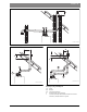
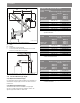
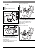
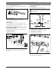
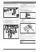
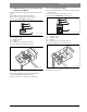
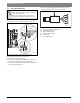
Table Of Contents
- Contents
- 1 Key to symbols and safety instructions
- 1.1 Key to symbols
- 1.2 General safety instructions
- 2 Scope of delivery
- 3 Information about the appliance
- 3.1 Proper use
- 3.2 Overview of boiler types
- 3.3 Rating plate
- 3.4 Appliance description
- 3.5 Accessories
- 3.6 Product dimensions and minimum clearances
- 3.7 Appliance layout heating boiler ZBR..-3A
- 3.8 Appliance layout combi boiler ZWB..-3A
- 3.9 Electrical wiring heating boiler ZBR..-3A
- 3.10 Electrical wiring combi boiler ZWB..-3A
- 3.11 Technical data heating boiler ZBR16-3A...
- 3.12 Technical data heating boiler ZBR21-3A...
- 3.13 Technical data heating boiler ZBR28-3A...
- 3.14 Technical data heating boiler ZBR35-3A...
- 3.15 Technical data heating boiler ZBR42-3A...
- 3.16 Technical data combi boiler ZWB28-3A...
- 3.17 Technical data combi boiler ZWB35-3A...
- 3.18 Technical data combi boiler ZWB42-3A...
- 3.19 Condensate composition
- 4 Regulations
- 5 Common Applications of ZBR boilers
- 6 Installation
- 6.1 Notes on installation and operation
- 6.1.1 Notes on installation and operation
- Fill and make-up water for the heating system
- Recommended steps for commissioning a new or retrofit boiler installation
- Recirculation pump/DHW recirculation lines
- Open vented heating systems
- Gravity heating systems
- Galvanized radiators or pipes.
- Plastic pipework
- Use of a room temperature control
- Primary-secondary piping or a low loss header
- Water Chemistry Guidelines
- Corrosion inhibitors
- Boiler sealer
- LPG
- 6.1.2 Other important information
- 6.1.1 Notes on installation and operation
- 6.2 Comparing the size of the integrated expansion vessel
- 6.3 ZBR..-3A appliances (heating boilers): Selecting an expansion vessel
- 6.4 Selecting the installation location
- 6.5 Pre-installing pipes
- 6.6 Mounting the appliance
- 6.7 Installing a low water cut off (LWCO)
- 6.8 Connecting flue gas accessories
- 6.9 Testing gas and water connections for leaks
- 6.1 Notes on installation and operation
- 7 Making the electrical connections
- 7.1 General notes
- 7.2 Low voltage electrical connections in the Heatronic boiler control
- 7.3 Electrical connections in the junction box (120 VAC)
- 7.4 Connecting the LWCO device
- 8 Commissioning
- 8.1 Before operating the appliance
- 8.2 Switching the appliance ON/OFF
- 8.3 Setting up space heating
- 8.4 Programming the FW 200 heating control unit
- 8.5 FW 200 heating control quick start
- 8.6 After commissioning
- 8.7 ZBR..-3A appliances (heating boilers) with DHW tank: Setting the DHW temperature
- 8.8 ZWB..-3A appliances (combi boilers): Setting the DHW temperature
- 8.9 Setting manual summer mode
- 8.10 Setting frost protection
- 8.11 Activating the key pad lock
- 9 ZBR..-3A appliances (heating boiler) with DHW tank: Thermal disinfection
- 10 Boiler circulator
- 11 Heatronic boiler control settings
- 11.1 Guideline to service functions
- 11.2 Overview of the service functions
- 11.3 Description of the service functions
- 11.3.1 First service level
- Service function 1.A: Maximum space heating output
- Service function 1.b: Maximum DHW output
- Service function 1.E: Pump mode for space heating operation
- Service function 1. F: Pump mode (only heating boiler ZBR..-3A)
- Service function 2.A: Heating circuit pump lockout time (only heating boiler ZBR..-3A)
- Service function 2.b: Maximum supply temperature
- Service function 2.C: Purging function
- Service function 2.d: Thermal disinfection (legionella protection)
- Service function 2.F: Operating mode
- Service function 3.A: Automatic anti-cycle function
- Service function 3.b: Set anti-cycle time
- Service function 3.C: Switching differential
- Service function 3.d: Minimum output (heating and DHW)
- Service function 3.E: Cycle time, keeping DHW hot (only combi boiler ZWB..-3A)
- Service function 3.F: Constant DHW period (only combi boiler ZWB..-3A)
- Service function 4.b: Maximum heat exchanger temperature (only combi boiler ZWB..-3A)
- Service function 4.d: Audible fault warning tone
- Service function 4.E: Appliance type
- Service function 4.F: Condensate trap filling sequence
- Service function 5.A: Reset inspection interval
- Service function 5.b: Fan post purge time
- Service function 5.E: Functionality of black plug in boiler junction box
- Service function 5.F: Set inspection interval
- Service function 6.A: Display the latest fault code
- Service function 6.b: Room temperature control, current voltage, terminal 2
- Service function 6.C: Supply temperature required by outdoor reset control
- Service function 6.d: Current DHW turbine flow rate (only combi boiler ZWB..-3A)
- Service function 7.A: Indicator lamp for burner operation / faults
- Service function 7.b: 3-way valve in center position
- Service function 7.d: Connecting an external supply or low-loss header temperature sensor
- Service function 7.E: Building drying function
- Service function 0.A: Do not use this setting!
- Service function 0.d: Altitude adjustment
- Service function 0.E: Metric or US customary units
- 11.3.2 Second service level
- Service function 8.A: Software version
- Service function 8.b: Code plug number
- Service function 8.C: GFA Gas burner control unit status
- Service function 8.d: GFA Gas burner control unit fault
- Service function 8.E: Restore boiler to factory settings
- Service function 8.F: Permanent ignition
- Service function 9.A: Constant mode
- Service function 9.b: Current fan speed
- Service function 9.C: Current boiler output
- Service function 9.d: Set fan start speed
- Service function 9.E: Turbine signal delay (only combi boiler ZWB..-3A)
- Service function 9.F: Heating zone pump post purge
- Service function A.b: Display DHW temperature
- Service function A.C: Display DHW tank temperature
- Service function b.F: Solar DHW backup heating delay (only combi boiler ZWB..-3A)
- Service function C.d: Display current heat demand
- 11.3.1 First service level
- 12 Gas type conversion
- 13 Flue gas test
- 14 Environmental responsibility/disposal
- 15 Inspection and maintenance
- Heat exchanger
- Heatronic boiler control
- Notes on installation and operation
- After the inspection/maintenance
- 15.1 Description of various steps
- 15.1.1 Calling up the latest fault (service function 6.A)
- 15.1.2 Fresh water filter (only combi boiler ZWB..-3A)
- 15.1.3 Plate type heat exchanger (only combi boiler ZWB..-3A)
- 15.1.4 Checking the electrodes
- 15.1.5 Burner servicing
- 15.1.6 Heat exchanger block inspection and cleaning
- 15.1.7 Condensate trap cleaning
- 15.1.8 Checking the mixer diaphragm
- 15.1.9 Expansion vessel
- 15.1.10 Setting the boiler water pressure
- 15.1.11 Testing system water quality
- 15.1.12 Inspecting electrical wiring
- 15.2 Checklist for inspection and maintenance
- 16 Readings on the display
- 17 Faults
- 18 Commissioning log for the appliance
- 19 Spare parts
- Index

Making the electrical connections | 45
6 720 806 992 (2013/09)Greenstar
Ø 3" / Ø 5" (Ø 80/125 mm) Concentric venting system
The maximum concentric pipe length ( tab. 23) depends on the
installation situation, the appliance type and the number of elbows used.
Example:
• Model: ZBR28-3A
• 90 ° elbows used: 2
• 45 ° elbows used: 2
Maximum straight vent pipe allowed: 38ft (11.6 m)
6.9 Testing gas and water connections for leaks
Water connections
▶ Open the heating supply and return valves and fill the heating system.
▶ Check all connections for leakage (test pressure: Max. 30 psi (2.07
bar) on the pressure gauge).
Gas line
▶ Close the gas shutoff valve to protect the gas valve from damage.
▶ Check all connections for leakage (test pressure: Max. 60" W.C. (150 mbar)).
▶ Release pressure.
7 Making the electrical connections
7.1 General notes
Electrical components must be installed by a trained and certified
electrician and the installation must meet the National Electric Code as
well as all applicable local codes and regulations.
The boiler must be properly electrically grounded in accordance with the
requirements of the authority having jurisdiction or, in the absence of
such requirements with the National Electrical Code, ANSI/NFPA 70
and/or the Canadian Electrical Code Part I, CSA C221.1, Electrical
Code.
All appliance modulation, control and safety components are tested and
pre-wired for use.
Observe safety precautions and all rules and regulations required by
local code and the National Electric Code.
Fuses
The appliance is protected with a fuse. It is located on the circuit board
( Fig. 8, page 16).
Controls and modules
For installation and electrical connection of controls and modules, see
the installation instructions of the accessory.
Installations Fig. 40
Ø 3" / Ø 5"
(Ø 80/125 mm)
CONCENTRIC
PIPE
Maximum straight vent pipe length allowed for
Ø 3" / Ø 5" (Ø 80/125 mm) concentric pipe
Number of 90 °
elbows used
ZBR16-3A
ZBR21-3A
ZBR28-3A
ZWB28-3A
ZBR35-3A
ZWB35-3A
ZBR42-3A
ZWB42-3A
1 50 ft (15.2 m) 44 ft (13.4 m)
2 44 ft (13.4 m) 38 ft (11.6 m)
3 38 ft (11.6 m) 32 ft (9.8 m)
4 32 ft (9.8 m) 26 ft (7.9 m)
5 26 ft (7.9 m) 20 ft (6.1 m)
6 20 ft (6.1 m) 14 ft (4.3 m)
Table 23 Pipe lengths with Ø 3" / Ø 5" (Ø 80/125 mm) diameter and
termination
Fitting Equivalent
ft m
45 ° elbow 3 0.91
90 ° elbow 6 1.82
Table 24 Concentric pipe friction loss equivalent for fittings
NOTICE: System damage!
Pressure, control and safety equipment may be
damaged by excessive pressure.
▶ When you carry out a leakage test, make sure that no
pressure, control or safety equipment is installed that
cannot be isolated from the test pressure.
▶ The boiler and its dedicated shutoff valve must be
disconnected from the gas supply piping system
during any pressure testing of that system at test
pressures in excess of 14" W.C. (35 mbar).
DANGER: Risk of electric shock!
▶ Before working on the power supply (120 VAC),
disconnect the boiler from the grid by shutting off the
emergency shutoff switch or disengaging the heating
system circuit breaker. Take measures to prevent
accidental reconnection.
▶ It is not sufficient to simply shut off the controls.
▶ Observe all applicable electrical codes and
regulations.
Provide a dedicated circuit breaker for the boiler and
heating system rated at least 15A. All line voltage wiring
must use at least AWG14 size cables.
Replacement fuses can be found on the back of the cover
( Fig. 42).