
Install Instructions
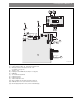
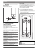
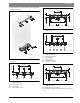
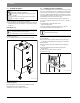
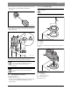
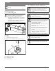
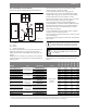
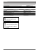
Table Of Contents
- Contents
- 1 Key to symbols and safety instructions
- 1.1 Key to symbols
- 1.2 General safety instructions
- 2 Scope of delivery
- 3 Information about the appliance
- 3.1 Proper use
- 3.2 Overview of boiler types
- 3.3 Rating plate
- 3.4 Appliance description
- 3.5 Accessories
- 3.6 Product dimensions and minimum clearances
- 3.7 Appliance layout heating boiler ZBR..-3A
- 3.8 Appliance layout combi boiler ZWB..-3A
- 3.9 Electrical wiring heating boiler ZBR..-3A
- 3.10 Electrical wiring combi boiler ZWB..-3A
- 3.11 Technical data heating boiler ZBR16-3A...
- 3.12 Technical data heating boiler ZBR21-3A...
- 3.13 Technical data heating boiler ZBR28-3A...
- 3.14 Technical data heating boiler ZBR35-3A...
- 3.15 Technical data heating boiler ZBR42-3A...
- 3.16 Technical data combi boiler ZWB28-3A...
- 3.17 Technical data combi boiler ZWB35-3A...
- 3.18 Technical data combi boiler ZWB42-3A...
- 3.19 Condensate composition
- 4 Regulations
- 5 Common Applications of ZBR boilers
- 6 Installation
- 6.1 Notes on installation and operation
- 6.1.1 Notes on installation and operation
- Fill and make-up water for the heating system
- Recommended steps for commissioning a new or retrofit boiler installation
- Recirculation pump/DHW recirculation lines
- Open vented heating systems
- Gravity heating systems
- Galvanized radiators or pipes.
- Plastic pipework
- Use of a room temperature control
- Primary-secondary piping or a low loss header
- Water Chemistry Guidelines
- Corrosion inhibitors
- Boiler sealer
- LPG
- 6.1.2 Other important information
- 6.1.1 Notes on installation and operation
- 6.2 Comparing the size of the integrated expansion vessel
- 6.3 ZBR..-3A appliances (heating boilers): Selecting an expansion vessel
- 6.4 Selecting the installation location
- 6.5 Pre-installing pipes
- 6.6 Mounting the appliance
- 6.7 Installing a low water cut off (LWCO)
- 6.8 Connecting flue gas accessories
- 6.9 Testing gas and water connections for leaks
- 6.1 Notes on installation and operation
- 7 Making the electrical connections
- 7.1 General notes
- 7.2 Low voltage electrical connections in the Heatronic boiler control
- 7.3 Electrical connections in the junction box (120 VAC)
- 7.4 Connecting the LWCO device
- 8 Commissioning
- 8.1 Before operating the appliance
- 8.2 Switching the appliance ON/OFF
- 8.3 Setting up space heating
- 8.4 Programming the FW 200 heating control unit
- 8.5 FW 200 heating control quick start
- 8.6 After commissioning
- 8.7 ZBR..-3A appliances (heating boilers) with DHW tank: Setting the DHW temperature
- 8.8 ZWB..-3A appliances (combi boilers): Setting the DHW temperature
- 8.9 Setting manual summer mode
- 8.10 Setting frost protection
- 8.11 Activating the key pad lock
- 9 ZBR..-3A appliances (heating boiler) with DHW tank: Thermal disinfection
- 10 Boiler circulator
- 11 Heatronic boiler control settings
- 11.1 Guideline to service functions
- 11.2 Overview of the service functions
- 11.3 Description of the service functions
- 11.3.1 First service level
- Service function 1.A: Maximum space heating output
- Service function 1.b: Maximum DHW output
- Service function 1.E: Pump mode for space heating operation
- Service function 1. F: Pump mode (only heating boiler ZBR..-3A)
- Service function 2.A: Heating circuit pump lockout time (only heating boiler ZBR..-3A)
- Service function 2.b: Maximum supply temperature
- Service function 2.C: Purging function
- Service function 2.d: Thermal disinfection (legionella protection)
- Service function 2.F: Operating mode
- Service function 3.A: Automatic anti-cycle function
- Service function 3.b: Set anti-cycle time
- Service function 3.C: Switching differential
- Service function 3.d: Minimum output (heating and DHW)
- Service function 3.E: Cycle time, keeping DHW hot (only combi boiler ZWB..-3A)
- Service function 3.F: Constant DHW period (only combi boiler ZWB..-3A)
- Service function 4.b: Maximum heat exchanger temperature (only combi boiler ZWB..-3A)
- Service function 4.d: Audible fault warning tone
- Service function 4.E: Appliance type
- Service function 4.F: Condensate trap filling sequence
- Service function 5.A: Reset inspection interval
- Service function 5.b: Fan post purge time
- Service function 5.E: Functionality of black plug in boiler junction box
- Service function 5.F: Set inspection interval
- Service function 6.A: Display the latest fault code
- Service function 6.b: Room temperature control, current voltage, terminal 2
- Service function 6.C: Supply temperature required by outdoor reset control
- Service function 6.d: Current DHW turbine flow rate (only combi boiler ZWB..-3A)
- Service function 7.A: Indicator lamp for burner operation / faults
- Service function 7.b: 3-way valve in center position
- Service function 7.d: Connecting an external supply or low-loss header temperature sensor
- Service function 7.E: Building drying function
- Service function 0.A: Do not use this setting!
- Service function 0.d: Altitude adjustment
- Service function 0.E: Metric or US customary units
- 11.3.2 Second service level
- Service function 8.A: Software version
- Service function 8.b: Code plug number
- Service function 8.C: GFA Gas burner control unit status
- Service function 8.d: GFA Gas burner control unit fault
- Service function 8.E: Restore boiler to factory settings
- Service function 8.F: Permanent ignition
- Service function 9.A: Constant mode
- Service function 9.b: Current fan speed
- Service function 9.C: Current boiler output
- Service function 9.d: Set fan start speed
- Service function 9.E: Turbine signal delay (only combi boiler ZWB..-3A)
- Service function 9.F: Heating zone pump post purge
- Service function A.b: Display DHW temperature
- Service function A.C: Display DHW tank temperature
- Service function b.F: Solar DHW backup heating delay (only combi boiler ZWB..-3A)
- Service function C.d: Display current heat demand
- 11.3.1 First service level
- 12 Gas type conversion
- 13 Flue gas test
- 14 Environmental responsibility/disposal
- 15 Inspection and maintenance
- Heat exchanger
- Heatronic boiler control
- Notes on installation and operation
- After the inspection/maintenance
- 15.1 Description of various steps
- 15.1.1 Calling up the latest fault (service function 6.A)
- 15.1.2 Fresh water filter (only combi boiler ZWB..-3A)
- 15.1.3 Plate type heat exchanger (only combi boiler ZWB..-3A)
- 15.1.4 Checking the electrodes
- 15.1.5 Burner servicing
- 15.1.6 Heat exchanger block inspection and cleaning
- 15.1.7 Condensate trap cleaning
- 15.1.8 Checking the mixer diaphragm
- 15.1.9 Expansion vessel
- 15.1.10 Setting the boiler water pressure
- 15.1.11 Testing system water quality
- 15.1.12 Inspecting electrical wiring
- 15.2 Checklist for inspection and maintenance
- 16 Readings on the display
- 17 Faults
- 18 Commissioning log for the appliance
- 19 Spare parts
- Index

32 | Installation
Greenstar6 720 806 992 (2013/09)
6 Installation
6.1 Notes on installation and operation
When installing and operating the heating system observe the following:
• The elevation of the installation location above sea level must be taken
into account ( Chapter 12.2).
• Follow all local building regulations regarding the installation
conditions on site.
• The local building regulations regarding air supply and venting
systems and the chimney flue connection.
• Electrical code requirements for connection to the electrical power
supply.
• The technical regulations of the gas company regarding the
connection of the gas burner to the local gas main.
• The regulations and standards relating to the DHW heating system.
6.1.1 Notes on installation and operation
Fill and make-up water for the heating system
Unsuitable fill and make-up water can result in the heating system
scaling up or failing prematurely.
Recommended steps for commissioning a new or retrofit boiler
installation
▶ Flush the system with clean water.
▶ Isolate the boiler, fill the system with fresh water and a boiler cleaner,
run for 30 minutes to 1 hour. Under no circumstances may boiler
cleaner be pumped through the boiler.
▶ Thoroughly flush the system with fresh water. Ensure all zones and
loops are flushed.
▶ Empty out sediment traps.
▶ Systems containing antifreeze not approved by Bosch, must be
completely flushed to ensure no old fluid remains.
▶ Fill the system with fresh water and the proper amount of inhibitor.
▶ Verify the pH is within the proper range.
▶ Add additional inhibitor if pH is not within the proper range.
▶ Check pH annually.
▶ If using antifreeze, fill with approved antifreeze and fresh water.
▶ Always follow the cleaner, antifreeze, or additive manufacturer’s
instructions.
▶ Do not mix different manufacturer’s products
▶ Follow manufacturer’s data to determine the anti-freeze ratio for the
desired freeze protection temperature.
Recirculation pump/DHW recirculation lines
Electrical connection of the DHW recirculation pump
( page 48).
Connect the DHW recirculation line with the cold water inlet as close as
possible to the Hydraulics connection plate.
Open vented heating systems
▶ Convert open vented heating systems into closed systems.
Gravity heating systems
▶ Connect the appliance to the existing piping system via a low-loss
header with a sludge separator.
Galvanized radiators or pipes.
To prevent gas formation:
▶ Do not use galvanized radiators or pipes.
Plastic pipework
If using plastic pipework for the heating system (eg.underfloor/radiant
heating), the type of pipe that should be used must be oxygen tight.
Use of a room temperature control
▶ Do not install thermostatic valves on radiators in the primary room.
Primary-secondary piping or a low loss header
Radiant floor, panel radiator, multi zone and application systems
exceeding 70' (21 m) of 3/4" baseboard at a 20°F delta T and a flow rate
of 4.0 gpm plus the necessary supply and return piping, require primary-
secondary piping or a low loss header for hydraulic separation of the
system from the boiler.
Water Chemistry Guidelines
DANGER: Explosion!
▶ Close the gas cock prior to working on the gas train.
▶ Check for gas leaks after carrying out work on the gas
train.
Installation, power connection, connection on the gas
and flue gas side and commissioning must only be
carried out by a contractor certified for such work by the
state or local jurisdiction or the local gas or power utility.
Total length DHW/recirculation line Flow rate
33 ft (10 m) 0.66 gpm (2.5 l/min)
33 - 66 ft (10 - 20 m) 0.92 gpm (3.5 l/min)
66 - 98 ft (20 - 30 m) 1.32 gpm (5 l/min)
Table 13 Recommended flow rates
Use service function 6.d, to determine the current flow
rate ( page 62).
NOTICE: Insufficient antifreeze can accelerate
corrosion.
▶ Follow manufacturer's instructions on antifreeze
concentration.
▶ Frost protection level has to be checked annually
during the regular scheduled maintenance of the
condensing boiler.
NOTICE: System damage!
▶ It is the installer's responsibility to ensure that the
heating system is compatible with the boiler type and
size installed.
▶ pH-value of the heating water to be kept between 7
and 8.5.