
Install Instructions

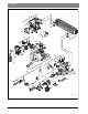


Table Of Contents
- Contents
- 1 Key to symbols and safety instructions
- 1.1 Key to symbols
- 1.2 General safety instructions
- 2 Scope of delivery
- 3 Information about the appliance
- 3.1 Proper use
- 3.2 Overview of boiler types
- 3.3 Rating plate
- 3.4 Appliance description
- 3.5 Accessories
- 3.6 Product dimensions and minimum clearances
- 3.7 Appliance layout heating boiler ZBR..-3A
- 3.8 Appliance layout combi boiler ZWB..-3A
- 3.9 Electrical wiring heating boiler ZBR..-3A
- 3.10 Electrical wiring combi boiler ZWB..-3A
- 3.11 Technical data heating boiler ZBR16-3A...
- 3.12 Technical data heating boiler ZBR21-3A...
- 3.13 Technical data heating boiler ZBR28-3A...
- 3.14 Technical data heating boiler ZBR35-3A...
- 3.15 Technical data heating boiler ZBR42-3A...
- 3.16 Technical data combi boiler ZWB28-3A...
- 3.17 Technical data combi boiler ZWB35-3A...
- 3.18 Technical data combi boiler ZWB42-3A...
- 3.19 Condensate composition
- 4 Regulations
- 5 Common Applications of ZBR boilers
- 6 Installation
- 6.1 Notes on installation and operation
- 6.1.1 Notes on installation and operation
- Fill and make-up water for the heating system
- Recommended steps for commissioning a new or retrofit boiler installation
- Recirculation pump/DHW recirculation lines
- Open vented heating systems
- Gravity heating systems
- Galvanized radiators or pipes.
- Plastic pipework
- Use of a room temperature control
- Primary-secondary piping or a low loss header
- Water Chemistry Guidelines
- Corrosion inhibitors
- Boiler sealer
- LPG
- 6.1.2 Other important information
- 6.1.1 Notes on installation and operation
- 6.2 Comparing the size of the integrated expansion vessel
- 6.3 ZBR..-3A appliances (heating boilers): Selecting an expansion vessel
- 6.4 Selecting the installation location
- 6.5 Pre-installing pipes
- 6.6 Mounting the appliance
- 6.7 Installing a low water cut off (LWCO)
- 6.8 Connecting flue gas accessories
- 6.9 Testing gas and water connections for leaks
- 6.1 Notes on installation and operation
- 7 Making the electrical connections
- 7.1 General notes
- 7.2 Low voltage electrical connections in the Heatronic boiler control
- 7.3 Electrical connections in the junction box (120 VAC)
- 7.4 Connecting the LWCO device
- 8 Commissioning
- 8.1 Before operating the appliance
- 8.2 Switching the appliance ON/OFF
- 8.3 Setting up space heating
- 8.4 Programming the FW 200 heating control unit
- 8.5 FW 200 heating control quick start
- 8.6 After commissioning
- 8.7 ZBR..-3A appliances (heating boilers) with DHW tank: Setting the DHW temperature
- 8.8 ZWB..-3A appliances (combi boilers): Setting the DHW temperature
- 8.9 Setting manual summer mode
- 8.10 Setting frost protection
- 8.11 Activating the key pad lock
- 9 ZBR..-3A appliances (heating boiler) with DHW tank: Thermal disinfection
- 10 Boiler circulator
- 11 Heatronic boiler control settings
- 11.1 Guideline to service functions
- 11.2 Overview of the service functions
- 11.3 Description of the service functions
- 11.3.1 First service level
- Service function 1.A: Maximum space heating output
- Service function 1.b: Maximum DHW output
- Service function 1.E: Pump mode for space heating operation
- Service function 1. F: Pump mode (only heating boiler ZBR..-3A)
- Service function 2.A: Heating circuit pump lockout time (only heating boiler ZBR..-3A)
- Service function 2.b: Maximum supply temperature
- Service function 2.C: Purging function
- Service function 2.d: Thermal disinfection (legionella protection)
- Service function 2.F: Operating mode
- Service function 3.A: Automatic anti-cycle function
- Service function 3.b: Set anti-cycle time
- Service function 3.C: Switching differential
- Service function 3.d: Minimum output (heating and DHW)
- Service function 3.E: Cycle time, keeping DHW hot (only combi boiler ZWB..-3A)
- Service function 3.F: Constant DHW period (only combi boiler ZWB..-3A)
- Service function 4.b: Maximum heat exchanger temperature (only combi boiler ZWB..-3A)
- Service function 4.d: Audible fault warning tone
- Service function 4.E: Appliance type
- Service function 4.F: Condensate trap filling sequence
- Service function 5.A: Reset inspection interval
- Service function 5.b: Fan post purge time
- Service function 5.E: Functionality of black plug in boiler junction box
- Service function 5.F: Set inspection interval
- Service function 6.A: Display the latest fault code
- Service function 6.b: Room temperature control, current voltage, terminal 2
- Service function 6.C: Supply temperature required by outdoor reset control
- Service function 6.d: Current DHW turbine flow rate (only combi boiler ZWB..-3A)
- Service function 7.A: Indicator lamp for burner operation / faults
- Service function 7.b: 3-way valve in center position
- Service function 7.d: Connecting an external supply or low-loss header temperature sensor
- Service function 7.E: Building drying function
- Service function 0.A: Do not use this setting!
- Service function 0.d: Altitude adjustment
- Service function 0.E: Metric or US customary units
- 11.3.2 Second service level
- Service function 8.A: Software version
- Service function 8.b: Code plug number
- Service function 8.C: GFA Gas burner control unit status
- Service function 8.d: GFA Gas burner control unit fault
- Service function 8.E: Restore boiler to factory settings
- Service function 8.F: Permanent ignition
- Service function 9.A: Constant mode
- Service function 9.b: Current fan speed
- Service function 9.C: Current boiler output
- Service function 9.d: Set fan start speed
- Service function 9.E: Turbine signal delay (only combi boiler ZWB..-3A)
- Service function 9.F: Heating zone pump post purge
- Service function A.b: Display DHW temperature
- Service function A.C: Display DHW tank temperature
- Service function b.F: Solar DHW backup heating delay (only combi boiler ZWB..-3A)
- Service function C.d: Display current heat demand
- 11.3.1 First service level
- 12 Gas type conversion
- 13 Flue gas test
- 14 Environmental responsibility/disposal
- 15 Inspection and maintenance
- Heat exchanger
- Heatronic boiler control
- Notes on installation and operation
- After the inspection/maintenance
- 15.1 Description of various steps
- 15.1.1 Calling up the latest fault (service function 6.A)
- 15.1.2 Fresh water filter (only combi boiler ZWB..-3A)
- 15.1.3 Plate type heat exchanger (only combi boiler ZWB..-3A)
- 15.1.4 Checking the electrodes
- 15.1.5 Burner servicing
- 15.1.6 Heat exchanger block inspection and cleaning
- 15.1.7 Condensate trap cleaning
- 15.1.8 Checking the mixer diaphragm
- 15.1.9 Expansion vessel
- 15.1.10 Setting the boiler water pressure
- 15.1.11 Testing system water quality
- 15.1.12 Inspecting electrical wiring
- 15.2 Checklist for inspection and maintenance
- 16 Readings on the display
- 17 Faults
- 18 Commissioning log for the appliance
- 19 Spare parts
- Index

Index | 101
6 720 806 992 (2013/09)Greenstar
(service function C.d) .......................................................... 64
Current heating output
(service function 9.C) .......................................................... 64
Current turbine flow rate (only ZWB..-3A)
(service function 6.d) .......................................................... 62
DHW heating delay (solar module)
(service function b.F) .......................................................... 64
DHW output
(service function 1.b) .......................................................... 59
DHW temperature
(service function A.b) .......................................................... 64
Display inspection
(service function 5.F) .......................................................... 62
Fan post purge time
(service function 5.b) .......................................................... 62
GFA fault
(service function 8.d) .......................................................... 63
GFA status
(service function 8.C) .......................................................... 63
Indicator lamp for burner operation / faults
(service function 7.A) .......................................................... 62
Last fault saved
(service function 6.A) .....................................................62, 69
Maximum heating output
(service function 1.A) .......................................................... 59
Maximum supply temperature
(service function 2.b) .......................................................... 60
Metric or US customary units
(service function 0.E) .......................................................... 63
Minimum heating/DHW output
(service function 3.d) .......................................................... 61
Operating mode
(service function 2.F) .......................................................... 60
Permanent ignition
(service function 8.F) .......................................................... 64
Pump control mode for heating operation
(service function 1.E) .......................................................... 59
Pump lockout time (only ZBR..-3A)
(service function 2.A) .......................................................... 60
Pump mode (only ZBR..-3A)
(service function 1.F) .......................................................... 59
Pump post purge time (heating)
(service function 9.F) .......................................................... 64
Reset service reminder
(service function 5.A) .......................................................... 62
Restore appliance (Heatronic 3) to factory settings
(service function 8.E) .......................................................... 64
Set functionality of black plug (connection NZ - LZ)
(service function 5.E) .......................................................... 62
Set start speed 1
(service function 9.d) .......................................................... 64
Software version
(service function 8.A) .......................................................... 63
Supply temperature required by outdoor reset control
(service function 6.C) .......................................................... 62
Switching differential
(service function 3.C) .......................................................... 61
Temperature at tank temperature sensor
(service function A.C) .......................................................... 64
Turbine signal delay (only ZWB..-3A)
(service function 9.E) .......................................................... 64
Voltage terminal 2
(service function 6.b) ...........................................................62
Service level
First service level ................................................................ 59
Second service level ............................................................ 63
Set functionality of black plug (connection NZ - LZ)....................... 62
Settings
Changing sensor curve of the heating pump............................. 57
Shutdown ............................................................................... 52
Spare Parts ............................................................................. 83
Steps for inspection and maintenance......................................... 69
Summer mode......................................................................... 55
Surface temperature ................................................................ 34
Switching the appliance OFF ..................................................... 52
Switching the appliance ON....................................................... 52
T
Technical data ................................................................... 18–25
ZBR16-3A.......................................................................... 18
ZBR21-3A.......................................................................... 19
ZBR28-3A.......................................................................... 20
ZBR35-3A.......................................................................... 21
ZBR42-3A.......................................................................... 22
ZWB28-3A... ...................................................................... 23
ZWB35-3A... ...................................................................... 24
ZWB42-3A... ...................................................................... 25
Technical specifications...................................................... 18–25
Testing gas line ........................................................................ 45
Testing water connections......................................................... 45
Thermal disinfection................................................................. 56
Turning the space heating ON .................................................... 52
Type of gas................................................................................ 7
Type overview ........................................................................... 7
W
Water Chemistry Guidelines ...................................................... 32
Z
ZBR..-3A................................................................................. 10
ZWB..-3A................................................................................ 12