
Installation Guide

AutoDome 100 Series Fixed Camera Cable and Wire Standards | en 67
Bosch Security Systems, Inc. Installation Manual F.01U.217.818 | 1.0 | 2011.04
5.5 Fiber Optic Module with an RS232/RS422 Controller
An AutoDome with a fiber optic module is prewired to operate with Biphase signals only. This
section describes the procedures necessary to control a VG5 series AutoDome fitted with a
fiber optic kit using an RS232 controller or a Pelco® RS422 controller.
To control a VG5 Series Autodome from an RS232 or from a Pelco RS422 controller you must
run control wires from the controller to an LTC 4629 head-end fiber optic module.
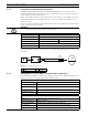
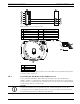
5.5.1 Connecting to an LTC 4629 Head End Data/Video Transceiver
1. Connect the RS232 cable (TxD from the controller) to the RS232 RxD port (pin 1) of the
LTC 4629.
2. Connect the ground wire of the controller to Pin 2 on the LTC 4629.
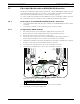
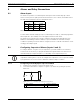
5.5.2 Configuring the VG5 AutoDome
1. Disconnect the power to the VG4 power supply unit; then open the unit.
2. Remove the green Serial Communications wire from the P106 connector.
3. Remove the 100 Ω resistor across the C+ and C- pins.
4. Cut the five wires from the green Serial Communications wire mating connector.
Ensure that the insulation covers each wire to avoid wires from touching.
5. Cut back the insulation on the blue (ground) wire and on the green (RxD) wire enough to
be able to connect these wires back into the P106 connector.
6. Connect the blue (ground) wire to the C- pin on the P106 connector.
7. Connect the green (RxD) wire to the C+ pin on the P106 connector.
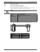
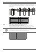
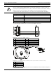
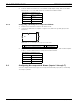
Figure 5.8 Detail of P106 Connections
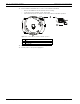
8. Connect the fiber optic cable from the AutoDome to the LTC 4629.
9. Close the door to the power supply unit.
1 Green RxD wire connected to C+
2 Blue Ground wire connected to C-
GND
T
XD
R
XD
C
+
C
-
24 VA
C
P
101
P106
P1
05
P10
7
X
F1
0
2
XF1
0
1
5 4
3
2
1
J
J
J103
J1
(
LED
)
HTR DOME
2
4V NC 24V
GND TXD RXD C+ C-