
Installation Guide

66 en | Cable and Wire Standards AutoDome 100 Series Fixed Camera
F.01U.217.818 | 1.0 | 2011.04 Installation Manual Bosch Security Systems, Inc.
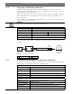
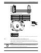
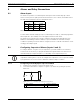
The following figure illustrates the connections for RS485 connections.
Figure 5.6 Connections for RS485 Operations
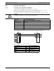
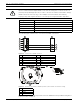
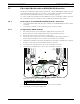
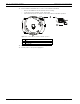
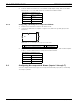
Figure 5.7 Position of CPU Switch for RS485 Operation (camera module not shown for clarity)
Note: To access the CPU switch you must remove the bubble from the pendant housing. Refer
to the procedure on Page 73.
CAUTION!
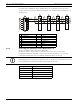
Bosch recommends that multiple RS485 connections be arranged as a connected series of
point-to-point (multi-dropped) nodes, as a line or as a bus. It is not recommended to arrange
RS485 connections as a star, ring, or as a multiple-connected network. Star and ring
topologies may cause signal reflections or excessively low or high termination impedance.
Wire Type 2-wire shielded twisted pair
Distance 1219 m (4000 ft)
Maximum Baud Rate 57.6 kb
Gage 0.511 mm (24 AWG)
Wire Impedance 120 W
Slide Switch Toward LEDs (factory default)
1 C- (Biphase) 7 AutoDome Data In/Out
2 C+ (Biphase) 8 P105/P106 Connector
3 Earth Ground 9 Head End RS485
4 RxD 10 Data +
5 TxD 11 Data -
6 Signal Ground 12 Ground
1 Switch Location
2LEDs
3RS485
4CPU Module
100 Ω