
Installation Guide

AutoDome 100 Series Fixed Camera Cable and Wire Standards | en 65
Bosch Security Systems, Inc. Installation Manual F.01U.217.818 | 1.0 | 2011.04
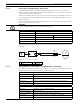
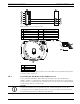
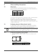
Figure 5.4 Connections for RS232 Operation
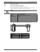
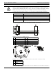
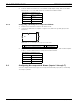
Figure 5.5 Position of CPU Switch for RS232 Operation (camera module not shown for clarity)
Note: To access the CPU switch you must remove the bubble from the pendant housing. Refer
to the procedure on Page 73.
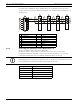
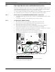
5.4.3 Controlling the AutoDome via the RS485 Protocol
2-wire (shielded), half-duplex, differential, multi-drop (32 nodes), 4000 ft cable limit)
RS485 is capable of controlling a true multi-drop network and is specified for up to 32 drivers
and 32 receivers on a single 2-wire bus. The AutoDome uses the 2-wire mode, although RS485
can be connected in a 2- or 4-wire mode.
1 C- (Biphase) 7 AutoDome Data In/Out
2 C+ (Biphase) 8 P105/P106 Connector
3 Earth Ground 9 Head End RS232
4 RxD 10 TxD
5TxD 11 RxD
6 Signal Ground 12 Ground
1 Switch Location
2LEDs
3RS232
4CPU Module
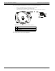
NOTICE!
The wire shield must be tied to signal at both ends, if 2-wire twisted pair is used. After
connecting the wires for RS485 operation, make sure the slide switch on the main board to
the camera head is positioned toward the LEDs (default).