
Installation Guide

64 en | Cable and Wire Standards AutoDome 100 Series Fixed Camera
F.01U.217.818 | 1.0 | 2011.04 Installation Manual Bosch Security Systems, Inc.
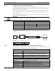
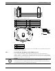
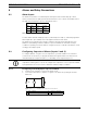
In a daisy chain configuration, where multiple domes are connected in series, the 100 Ω
resistor must be removed from all but the last dome. You can daisy chain a maximum of four
(4) AutoDomes.
Figure 5.3 Connections for a Daisy Chain Configuration
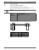
5.4.2 Controlling the AutoDome via the RS232 Protocol
(3-wire, full-duplex, single-ended, 50 ft. cable limit)
RS232 is a common, single-ended communication protocol used for control. Data
transmission via 3-wires (TDX, RXD, common) is from one transmitter to one receiver at
relatively slow baud rates (up to 57.6 Kbaud) and short distances up to 50 ft.
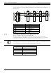
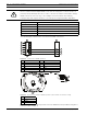
1 C- (Biphase) 9 Dome 3
2 C+ (Biphase) 10 Dome 2
3 Earth Ground 11 Dome 1
4 RxD 12 Head End Biphase
5 TxD 13 C- (Biphase)
6 Signal Ground 14 C + (Biphase)
7 Last Dome Data In/Out 15 Shield
8 P105/P106 Connector
100 Ω
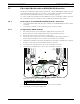
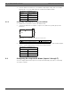
NOTICE!
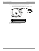
After making the wire connections for RS232 operation, reposition the slide switch located on
the CPU Module to the camera head inward and away from the LEDs.
Wire Type 3-wire (TXD, RXD, common)
Distance 15 m (50 ft)
Maximum Baud Rate 57.6 Kb
Voltage ± 15 V
Termination 100 Ω
Slide Switch Away from LEDs (factory default)