
Installation Guide


AutoDome 100 Series Fixed Camera Installing the In-Ceiling Mount | en 57
Bosch Security Systems, Inc. Installation Manual F.01U.217.818 | 1.0 | 2011.04
8. To connect supervised alarms and relays, attach the appropriate wires to their terminals
on the P104 connector on the Pipe Interface Board. Refer to Section 6 Alarms and Relay
Connections, page 69 for more details on wiring alarms.
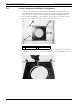
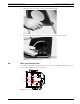
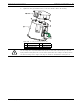
9. Attach the lid to the Interface box:
a. Align the slots on the lid with the two posts at the rear of the Interface box.
b. Rotate the lid down.
c. Squeeze the ground clips, located at the front of the box, against the Interface box
with your fingers before closing the lid to ensure that the lid does not catch on the
ground clips.
d. Secure the lid to the Interface box by pushing the lid down until the clip on the lid
catches against the box.
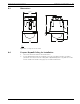
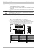
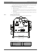
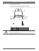
4.6.2 Interface Box Connections
The following figure is a detailed illustration of the In-ceiling Interface box.
Figure 4.8 In-ceiling Interface Box
1 Fiber Optics 5 Coax Video
2 UTP/Ethernet Video
(Ethernet for VG5 700 Series only)
6Alarm In
3 Dome Power 7 Analog In
4 Data In/Out 8 Relay
P105
P104
P102
P103
J101
J102
24VAC
24VAC
P101
SIG GND
TXD (-)
RXD (+)
C +
C -
NC
NO
COM
AGND
A2
A1
J103
A3
A4
A5
A6
A7
AGND
AGND
OUT3
OUT2
OUT1