
Installation Guide


56 en | Installing the In-Ceiling Mount AutoDome 100 Series Fixed Camera
F.01U.217.818 | 1.0 | 2011.04 Installation Manual Bosch Security Systems, Inc.
4.6.1 Make the Connections
After routing all video, control, power, and alarm wires:
1. Attach a 3/4-inch NPS (20-mm) conduit fitting to the hole in which you bring in the wires.
Be sure to thread the inside nut to the conduit fitting.
2. Route the video, control, power, and alarm wires through the conduit fitting and into the
Interface Box.
3. Cut and trim the wires allowing for sufficient slack to their respective terminals in the
box.
4. Attach the remaining control data in/out wires to their respective terminals in the
Interface Box. Refer to Table 4.1, Page 58, for terminal connections.
5. If using UTP for video, you must attach an RJ45 connector plug to the incoming UTP cable
and connect it to its matting connector J101 in the Interface Box. Refer to
Section 5 Cable and Wire Standards, page 61 for specifications.
Note: Do not connect the RJ45 connector unless using UTP video.
6. Connect the 24 VAC power wires to the P101 connector in the Interface Box.
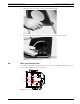
7. To connect alarm inputs and outputs, attach the supplied 6-pin Alarms In and the 4-pin
Alarms Out connector plugs with flying leads to the appropriate alarm wires. Then
connect the plugs to their mating connectors P103 and P102 in the Interface Box.
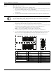
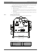
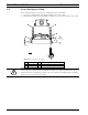
Figure 4.7 Alarm and Relay Connector Plugs
NOTICE!
If installing the dome to a drywall ceiling, allow enough wire to make the connections in the
Interface Box below the ceiling. Refer to Figure 4.6, Page 55, for connector locations and
Table 4.1, Page 58, for wire connections.
1 4-pin Alarm Connector
(P102)
2
*
6-pin Alarm In Connector
(P103)
3 7-pin Relay Connector
(P104)
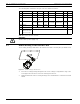
Pin Description Pin Description Pin Description
1 Alarm Out 1 1 Alarm In 3 1 Normally Open
2 Alarm Out 2 2 Alarm In 4 2 COM
3 Alarm Out 3 3 Alarm In 5 3 Normally Closed
4 Alarm Ground 4 Alarm In 6 4 Earth Ground
5 Alarm In 7 5 Analog Alarm 1
6 Alarm Ground 6 Analog Alarm 2
* Low Voltage TTL (3.3V) can also be used.
7Ground
1
1
2
3
4
5
6
2
3
4
N.O. COM N.C. A1 GND A2
1
PIN
PIN
P102
P103
P104
WHITE
ORANGE
BROWN
GREEN
WHITE
ORANGE
BROWN
GREEN
YELLOW
BLUE
2
3
4
5
6
7