
Installation Guide


48 en | Installing Roof Parapet and Pipe Mounts AutoDome 100 Series Fixed Camera
F.01U.217.818 | 1.0 | 2011.04 Installation Manual Bosch Security Systems, Inc.
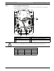
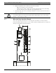
3.7.2 Connecting Wires to the Pipe Interface Board
The Pipe Interface Board contains all of the connectors for control, data, image, and power
wires. Follow the procedures below to make the proper connections.
1. Attach a BNC connector to the video coax cable and connect it to its mating connector
J102 on the Pipe Interface Board.
2. If using UTP for video, attach an RJ45 connector plug to the UTP cable and connect the
plug to its mating connector J101 on the Pipe Interface Board.
3. Attach the control data in/out wires to their respective terminals on the P105 connector
on the Pipe Interface Board. Refer to Figure 3.10, Page 46, for an illustration of these
connections.
4. Connect the 24 VAC power wires to the P101 connector on the Pipe Interface Board. If
this model has a heater, connect the 24 VAC heater power wires to connector P107.
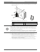
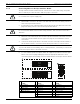
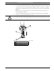
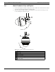
5. To connect alarm inputs and outputs, attach the supplied 6-pin Alarms In and the 4-pin
Alarms Out connector plugs with flying leads to the appropriate alarm wires. Then
connect the plugs to their mating connectors P103 and P102 on the Pipe Interface Board.
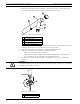
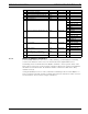
Figure 3.11 Alarm and Relay Connector Plugs
WARNING!
Use a 24 VAC Class 2 power supply only.
WARNING!
Do not connect the RJ45 connector unless using UTP video. This connection causes video
distortion.
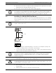
CAUTION!
To protect the AutoDome from damage due to cold temperatures, ensure that you connect the
24 VAC heater power wires to the P101 connector.
1 4-pin Alarm Connector
(P102)
2 6-pin Alarm In Connector
(P103)
3 7-pin Relay Connector
(P104)
Pin Description Pin Description Pin Description
1 Alarm Out 1 1 Alarm In 3 1 Alarm Out 4 Normally Open
2 Alarm Out 2 2 Alarm In 4 2 Alarm Out 4 COM
3 Alarm Out 3‡ 3 Alarm In 5 3 Alarm Out 4 Normally Closed
4 Alarm Ground 4 Alarm In 6 4 Earth Ground
5 Alarm In 7 5 Analog Alarm 1
6 Alarm Ground 6 Analog Alarm 2
7Ground
1
1
2
3
4
5
6
2
3
4
N.O. COM N.C. A1 GND A2
1
PIN
PIN
P102
P103
P104
WHITE
ORANGE
BROWN
GREEN
WHITE
ORANGE
BROWN
GREEN
YELLOW
BLUE
2
3
4
5
6
7